


PN25

Yoshitake GD-28S direct type pressure reducing valve for cold and hot water. Features a cast stainless steel body, 1.6 MPa max inlet pressure, and EPDM valve disc.
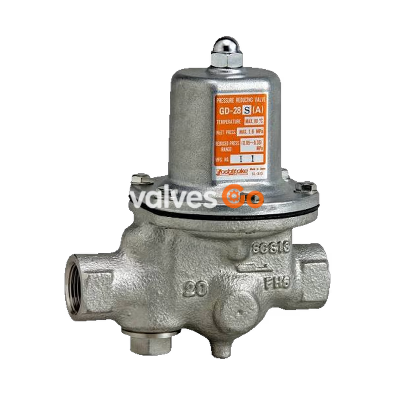
Yoshitake GD-28S is a direct type pressure reducing valve designed for cold and hot water applications. This compact and lightweight valve features a cast stainless steel body and an EPDM valve disc. It supports an inlet pressure of up to 1.6 MPa and provides a maximum pressure reduction ratio of 10:1. The wetted parts are made of corrosion-resistant materials to prevent rusty water.
| Specification | Value |
|---|---|
| Application | Cold and hot water |
| Inlet pressure | 1.6 MPa or less |
| Reduced pressure | (A) 0.05-0.35 MPa (B) 0.3-0.7 MPa |
| Minimum differential pressure | 0.05 MPa |
| Maximum pressure reduction ratio | 10:1 |
| Application temperature | 5-90°C |
| Body | Cast stainless steel |
| Valve seat | Cast stainless steel |
| Valve disc | EPDM |
| Connection | JIS Rc screwed |
INFO
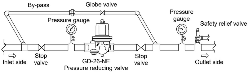
A strainer is not incorporated in this model. A strainer (40 mesh or more) is recommended to be installed at the inlet side. Pressure gauge connection port is JIS Rc 1/4 (select from φ42 - Max 1.0MPa, 0.4MPa, 0.2MPa).
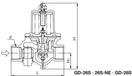
| Nominal size | d | L (mm) | H (mm) | H1 (mm) | Weight (kg) |
|---|---|---|---|---|---|
| 20A | Rc 3/4 | 135 | 170 | 41 | 2.2 |
| 25A | Rc 1 | 135 | 170 | 41 | 2.2 |
| 32A | Rc 1-1/4 | 180 | 224 | 57 | 4.7 |
| 40A | Rc 1-1/2 | 180 | 224 | 57 | 4.5 |
| 50A | Rc 2 | 200 | 239.5 | 61 | 6.5 |
The following table shows the rated flow rate when the differential pressure before and after the valve is 0.15 MPa or more.
| Nominal size | 20A | 25A | 32A | 40A | 50A |
|---|---|---|---|---|---|
| Rated flow rate (L/min) | 40 | 60 | 100 | 150 | 250 |
If the differential pressure before and after the valve is less than 0.15 MPa, refer to the flow rate chart.
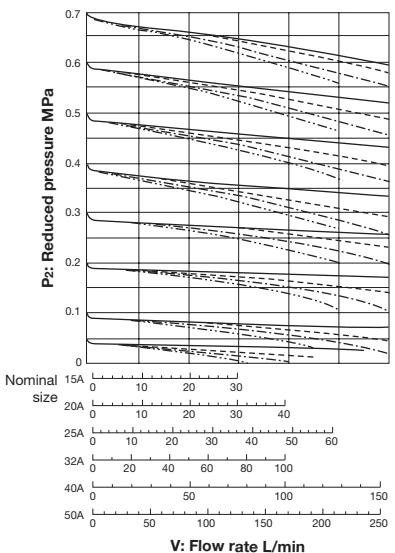
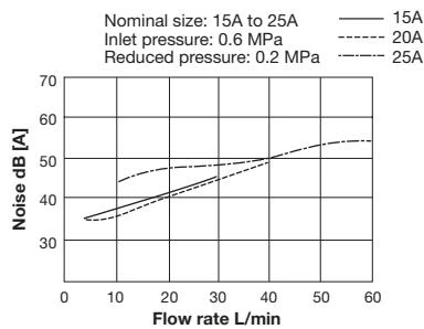
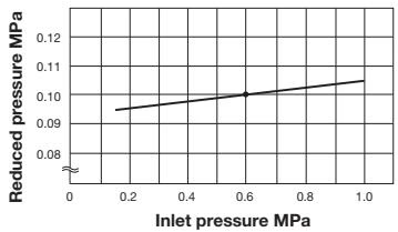
This chart shows variation in reduced pressure when the inlet pressure of 0.6 MPa is changed between 0.15 MPa and 1.0 MPa while the reduced pressure is set at 0.1 MPa.
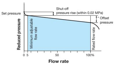
Offset pressure:
| Nominal size | Pressure range | Reduced pressure range | Offset pressure |
|---|---|---|---|
| 20A-50A | A | 0.05-0.35 MPa | Within 0.05 MPa |
| 20A-50A | B | 0.30-0.70 MPa | Within 0.10 MPa |
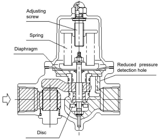
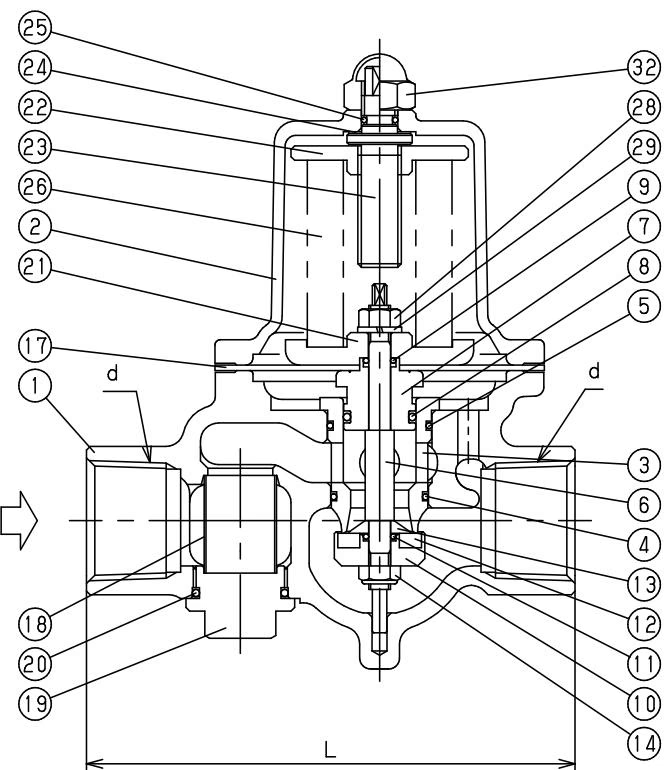
The spring is compressed by the adjusting screw, the diaphragm is pushed down, and thereby the disc directly connected to it is opened. Fluid coming in from the inlet side flows out from the upper part of the disc to the outlet side, and passes through the reduced pressure detection hole, and is led to the bottom of the diaphragm. The load of the spring and the reduced pressure act to the diaphragm, and the upper and lower force keeps a balance and regulates the valve opening. As a result, the diaphragm keeps the reduced pressure constant.
WARNING
TIP
To adjust the set pressure, turn the adjusting screw slowly. Failure to do so may result in damage to the product and other equipment due to hunting.
Yoshitake Control Valves / Pressure Reducing Valves
GP, GD, and CP series for stable pressure reduction and control in steam, water, and air systems.
Explore similar products in our catalog



