PN25
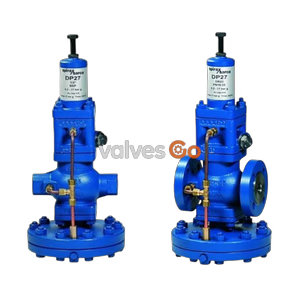
Yoshitake GP-1000 series pilot-operated pressure reducing valves for steam. Compliant with ANSI Class IV leak standard, features a robust ductile cast iron body, and provides stable pressure control up to 220℃.
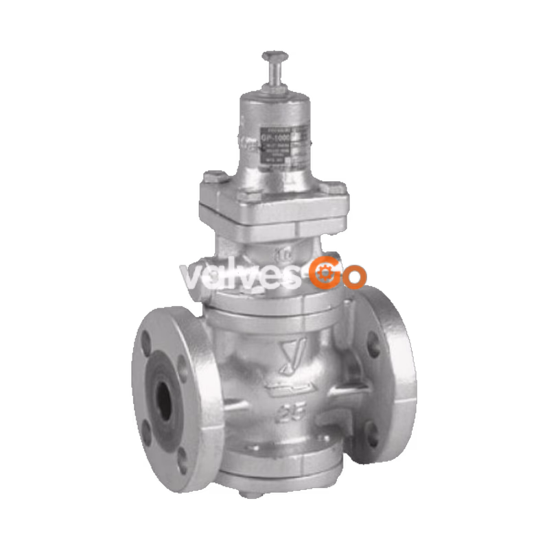
The Yoshitake GP-1000 Series pilot-operated pressure reducing valves for steam can be used with confidence for small to large flow rates in a host of applications ranging from building utilities systems, air-conditioning systems, and factory systems. The spherical main valve offers great sealability and a significant reduction in valve seat leakage (compliant with ANSI Class IV). It features a simple and robust internal structure and complies with SHASE-S106 standard for pressure reducing valves.
| Model | GP-1000 / 1010 | GP-1000SS | GP-1000H | GP-1002 / 1012 |
|---|---|---|---|---|
| Connection | Flanged (JIS 10K FF) / JIS Rc Screw | Flanged (JIS 10K FF) | Flanged (JIS 16K FF) | Flanged (JIS 10K FF) / JIS Rc Screw |
| Nominal size | 15 - 100A / 15 - 50A | 15 - 100A | 15 - 100A | 15 - 100A / 15 - 50A |
| Application | Steam | Steam | Steam | Steam |
| Inlet pressure | 0.1 - 1.0 MPa | 0.1 - 1.0 MPa | 0.1 - 1.6 MPa | 0.1 - 0.5 MPa |
| Reduced pressure | 0.05 - 0.9 MPa | 0.05 - 0.9 MPa | 0.05 - 0.9 MPa, 0.9 - 1.4 MPa | 0.03 - 0.15 MPa |
| Min. diff. pressure | 0.05 MPa | 0.05 MPa | 0.05 MPa | 0.05 MPa |
| Max. reducing ratio | 20:1 | 20:1 | 20:1 | 20:1 |
| Max. temperature | 220℃ | 220℃ | 220℃ | 220℃ |
| Valve seat leakage | 0.01% or less of rated flow | 0.01% or less of rated flow | 0.01% or less of rated flow | 0.01% or less of rated flow |
| Body material | Ductile cast iron | Stainless steel | Ductile cast iron | Ductile cast iron |
| Valve/Seat material | Stainless steel | Stainless steel | Stainless steel | Stainless steel |
| Piston/Cylinder | Brass or Bronze | Stainless steel | Brass or Bronze | Brass or Bronze |
INFO
Reduced pressure must be 90% or less of inlet pressure (gauge pressure).
| Size | L (mm) | H1 (mm) | H (mm) | Weight (kg) |
|---|---|---|---|---|
| 15A | 150 | 64 | 285 | 8.0 |
| 20A | 155 | 64 | 285 | 8.5 |
| 25A | 160 | 67 | 300 | 10.0 |
| 32A | 190 | 82 | 323 | 14.0 |
| 40A | 190 | 82 | 323 | 14.5 |
| 50A | 220 | 93 | 347 | 20.0 |
| 65A | 245 | 100 | 357 | 30.0 |
| 80A | 290 | 122 | 404 | 35.0 |
| 100A | 330 | 144 | 450 | 52.5 |
| Size | d | L (mm) | H1 (mm) | H (mm) | Weight (kg) |
|---|---|---|---|---|---|
| 15A | Rc 1/2 | 150 | 64 | 285 | 7.0 |
| 20A | Rc 3/4 | 155 | 64 | 285 | 7.0 |
| 25A | Rc 1 | 160 | 67 | 300 | 8.5 |
| 32A | Rc 1-1/4 | 190 | 82 | 323 | 12.0 |
| 40A | Rc 1-1/2 | 190 | 82 | 323 | 12.5 |
| 50A | Rc 2 | 220 | 93 | 347 | 18.0 |
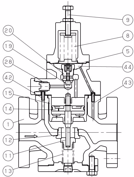
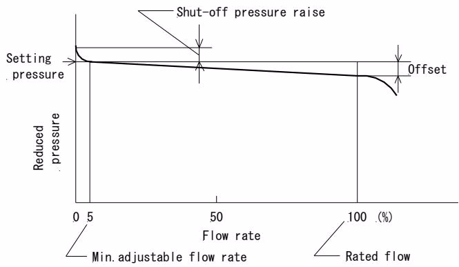
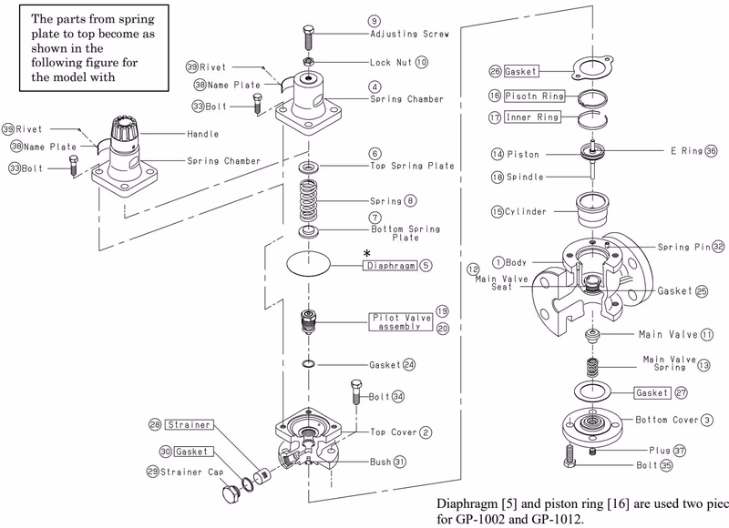
The pressure-reducing valve reduces pressure by throttling the valve. The valve is composed of the main valve and main valve seat for throttling, and adjusting spring, diaphragm, pilot valve, and piston for pressure sensing and activation.
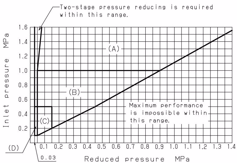
Find the intersection point of the inlet and reduced pressures. The GP-1000 series valves are suitable within ranges (A), (B), (C), and (D).
| Reduced pressures (MPa) | Safety valve setting pressure (MPa) |
|---|---|
| 0.03 - 0.1 | Reduced pressures + more than 0.05 |
| 0.1 - 0.4 | Reduced pressures + more than 0.08 |
| 0.4 - 0.6 | Reduced pressures + more than 0.1 |
| 0.6 - 0.8 | Reduced pressures + more than 0.12 |
| 0.8 - 1.4 | Reduced pressures + 15% |
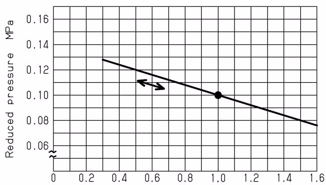 Reduced pressure is set to 0.1 MPa when inlet pressure is 1.0 MPa. The chart indicates a variation in reduced pressure when the inlet pressure is changed from 1.6 to 0.3 MPa.
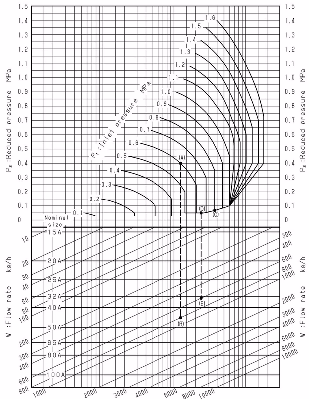
For example, take a pressure reducing valve whose inlet pressure (P1) is 0.6 MPa, reduced pressure (P2) is 0.4 MPa, flow rate 800 kg/h. First, find the point of intersection (A) of inlet pressure 0.6 MPa and reduced pressure 0.4 MPa. Vertically proceed from point (A) to come across the flow rate 800 kg/h, and regard this point as (B). Point (B) is between nominal sizes 40A and 50A. Select the larger nominal size 50A.
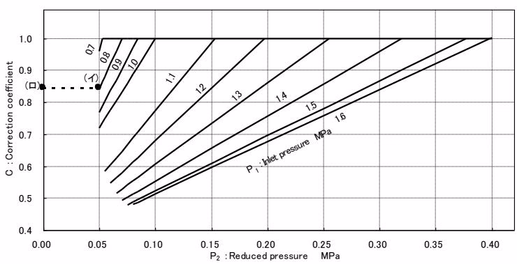
If the inlet pressure exceeds 0.7 MPa, and the pressure reducing is 0.4 MPa or less, find the appropriate correction coefficient C using the chart below, multiply the rated Cv value, and obtain the corrected Cv value.
| P1 (MPa) | P2 (MPa) | 15A | 20A | 25A | 32A | 40A | 50A | 65A | 80A | 100A |
|---|---|---|---|---|---|---|---|---|---|---|
| 1.0 | 0.05 | 92 | 212 | 369 | 600 | 831 | 1478 | 2310 | 3326 | 5913 |
| 1.0 | 0.1-0.4 | 132 | 303 | 528 | 858 | 1188 | 2112 | 3300 | 4752 | 8448 |
| 1.0 | 0.5 | 127 | 292 | 508 | 826 | 1145 | 2035 | 3180 | 4580 | 8142 |
| 1.0 | 0.8 | 87 | 200 | 349 | 566 | 785 | 1396 | 2181 | 3142 | 5585 |
| 0.8 | 0.1-0.3 | 108 | 248 | 432 | 702 | 972 | 1728 | 2700 | 3888 | 6912 |
| 0.8 | 0.5 | 92 | 212 | 370 | 601 | 833 | 1481 | 2314 | 3332 | 5915 |
| 0.6 | 0.1-0.2 | 84 | 193 | 336 | 546 | 756 | 1344 | 2100 | 3024 | 5376 |
| 0.6 | 0.4 | 67 | 155 | 270 | 439 | 608 | 1080 | 1690 | 2433 | 4326 |
| 0.4 | 0.1 | 60 | 138 | 240 | 390 | 540 | 960 | 1500 | 2160 | 3840 |
| 0.4 | 0.2 | 55 | 126 | 220 | 358 | 496 | 883 | 1380 | 1987 | 3532 |
| 0.2 | 0.1 | 30 | 70 | 123 | 200 | 277 | 493 | 771 | 1110 | 1974 |
INFO
When the inlet pressure is more than 0.7 MPa and the pressure reduction ratio is more than 10:1, calculate the corrected Cv value by multiplying the rated Cv value by the correction factor C.
WARNING
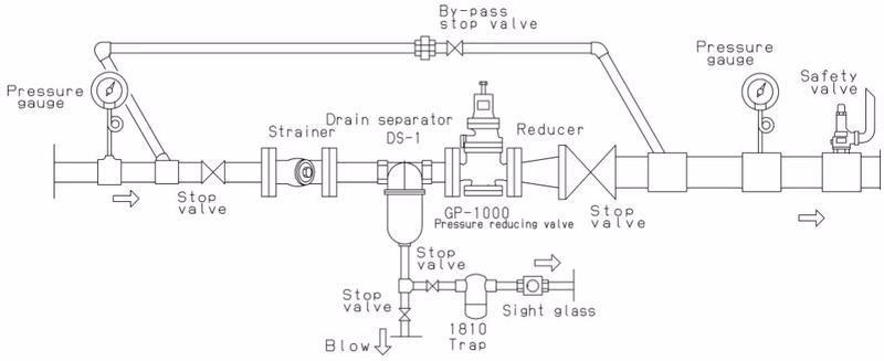
Because of heavy weight, hold the valve with lifting equipment while piping. Failure to do so may result in injury due to dropping the valve. In case installing a safety valve as a safety device at the outlet side, joint relief pipe at the outlet of the safety valve and guide it to a safe place where steam can relief out.
WARNING
Do not touch the valve directly with bare hands. Before flowing the steam in the pipe line, make sure steam can flow without any danger at the end of the pipe line and the pipe line is connected tightly.
| Problem | Cause | Solution |
|---|---|---|
| Pressure does not reach the desired value. | 1. Incorrect pressure is being used. 2. Strainer is clogged. 3. Foreign matter exists between piston and cylinder. 4. Piston ring is damaged. 5. Nominal size is too small. 6. Pressure is not adjusted correctly. 7. Strainer installed before valve is clogged. 8. Pressure gauge is faulty. | 1. Correct the pressure. 2. Disassemble and clean. 3. Remove foreign matter/polish scratches. 4. Replace piston ring. 5. Change nominal size. 6. Readjust pressure. 7. Disassemble and clean. 8. Replace it. |
| Reduced pressure raises above the specified value. | 1. Foreign matter exists between main valve and seat. 2. Foreign matter exists between pilot valve and seat. 3. Foreign matter exists between piston and cylinder. 4. Trap is not provided for dead-end. | 1. Remove foreign matter/lap seat. 2. Clean or replace pilot valve assembly. 3. Remove foreign matter/polish scratches. 4. Install a trap. |
| Abnormal noise is heard. | 1. Nominal size is too large. 2. Pressure reducing ratio is too large. 3. Drainage problem is caused. 4. Abrupt OPEN/CLOSE valve is too close. | 1. Change nominal size. 2. Reduce pressure in two stages. 3. Install a trap. 4. Allow at least 3 m between valves. |
Be sure that the stop valves at the inlet and outlet side of the pressure reducing valve are closed and all internal pressure and condensate have discharged before disassembling the valve.
TIP
Replace gaskets with new ones when reassembling. If the gasket is used for a long time, it may cause a steam leakage problem. Assemble in the reverse order of disassembly and tighten the bolts evenly.
Explore similar products in our catalog