


PN25

Armstrong GP-2000 externally piloted pressure reducing valve for steam service. Features ductile iron body, 20:1 rangeability, and ANSI Class IV shutoff.
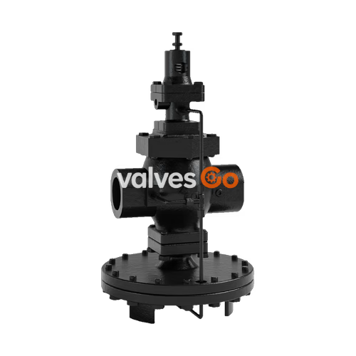
Armstrong GP-2000 is a high performance, externally piloted reducing valve for large capacity requirements. Typical use is on intermittent service, including applications such as heat exchangers, steam coils, rotating dryers, process equipment and heating systems. With a 20:1 rangeability and high Cv, the GP-2000 is reliable and accurate (+/-1% of pressure set point from 5% to 100% of flow) over a long, troublefree service life.
Hardened stainless steel working parts are renewable in-line. Single seated for dead-end service. Available with both NPT (1/2" - 2") and flanged connections in 1/2" - 6" sizes. ANSI Class IV Shutoff.
| Application | Inlet Pressure psig (bar) | Reduced Pressure psig (bar) | Spring Color | Maximum Temperature °F (°C) | Minimum Differential psig (bar) | Body Material | Main Valve/Seat | Pilot Valve/Seat | Diaphragm | Color |
|---|---|---|---|---|---|---|---|---|---|---|
| Steam | NPT 15-300 (1-20) | *1.5-3 (0.1-0.21) | Yellow | 450 (232) | 7 (0.48) | Ductile Iron ASTM A536 | Stainless Steel AISI 420 | Stainless Steel AISI 301 | Stainless Steel | Dark Gray |
| 150 lb. Flanged 15-185 (1-13) | 3-21 (0.21-1.4) | Yellow | ||||||||
| 300 lb. Flanged 15-300 (1-20) | 15-200 (1-13.8) | Green |
INFO
*NOTE: When using this spring range, remove one (1) pilot diaphragm. Capacities are reduced by 1/2 of capacity chart when this spring is being used. Maximum pressure reduction 20:1. Minimum pressure reduction is 85% of inlet pressure.
WARNING
This bulletin should be used by experienced personnel as a guide to the installation and maintenance of the Armstrong GP-2000 Pressure Reducing Valve.
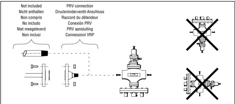
Model GP-2000:
Model GP-2000R:
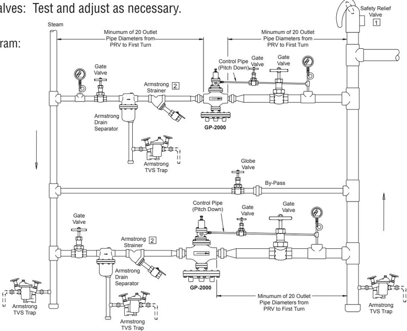
Step 1: Isolate all PRVs using gate valves Step 2: Open gate valve to top PRV. Set outlet pressure. Step 3: Re-Isolate all PRVs using gate valves Step 4: Open gate valve to bottom PRV. Set outlet pressure. Step 5: Open all gate valves: Test and adjust as necessary.
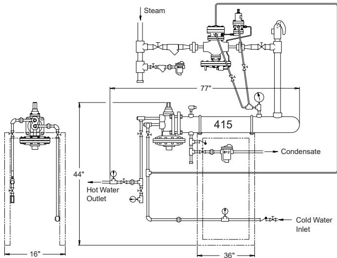
The Armstrong GP-2000W1P is a self-controlled shut down device avoiding the need for electricity to control systems, providing safe dependable shut down of the main steam valve when water pressure fails or drops rapidly on a fixed pressure steam water heater. The GP-2000W1P combination valve essentially lets the steam pressure modulate below the water pressure by 2 or 3 pounds, allowing a water heater to supply hot water even when water pressure is low.
TIP
Equipment under pressure - Operating temperature > 100°C. Make sure pressure reducing valve is cold before handling!
I. Pilot Valve Replacement:
II. Main Valve Replacement:
III. Main Diaphragm Replacement:
Explore similar products in our catalog



