


PN25

Yoshitake GD-24GS pressure reducing valve set for hot or cold water. Includes GD-24 valve, pressure gauge, and SY-24 strainer. Bronze body, JIS Rc 15-50A, max 1.6 MPa, up to 80°C.
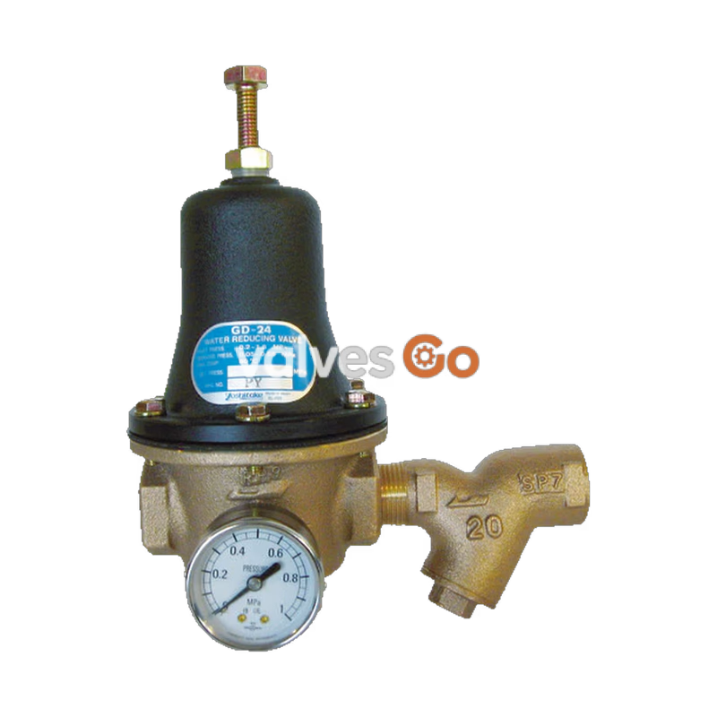
The Yoshitake GD-24GS is a pressure reducing valve designed for hot or cold water applications. It operates with an inlet pressure range of 0.2 to 1.6 MPa and a reduced pressure of 0.05 to 0.55 MPa, achieving a maximum pressure reducing ratio of 10:1. The GD-24GS is a complete set that includes the GD-24 pressure reducing valve, a pressure gauge, and an SY-24 strainer (with a 60-mesh screen).
INFO
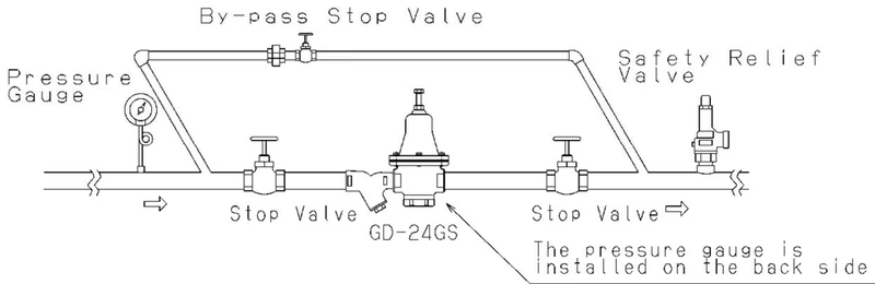
The pressure gauge and strainer are included with the product and must be attached to the pressure reducing valve when installing the piping on site. The valve can be mounted horizontally or vertically.
| Model | GD-24GS |
|---|---|
| Nominal size | 15~50A |
| Application (Fluid) | Hot or cold water |
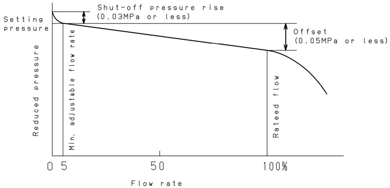
| Inlet pressure | 0.2~1.6 MPa |
| Reduced pressure | 0.05~0.55 MPa |
| Min. differential pressure | 0.05 MPa |
| Max. pressure reducing ratio | 10:1 |
| Temperature | 5~80℃ (*) |
| Connection | JIS Rc |
| Body Material | Bronze |
| Valve (Disc) Material | Urethane rubber |
| Valve Seat Material | Stainless steel |
| Diaphragm Material | NBR |
* Avoid continuous use at 70 ℃. The maximum temperature of the pressure gauge is 45°C. If the fluid temperature exceeds 45°C, protect the pressure gauge by using a siphon tube or similar. The accuracy of the pressure gauge is ±3.0%F.S.
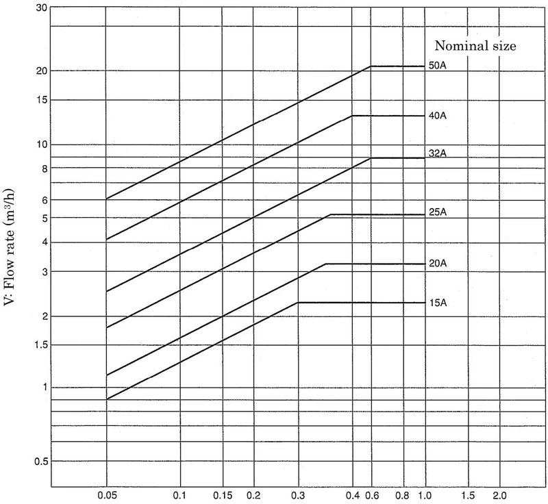
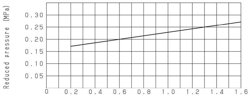
ΔP: Inlet/reduced pressure differential (MPa) Note: The chart shown above is for a GD-24 valve without SY-24. Considering factors such as noise and durability, a 2 m/s flow velocity within the pipe is ideal.
| Nominal size | 15A | 20A | 25A | 32A | 40A | 50A |
|---|---|---|---|---|---|---|
| Cv value | 1.5 | 1.9 | 3 | 4 | 7 | 10 |
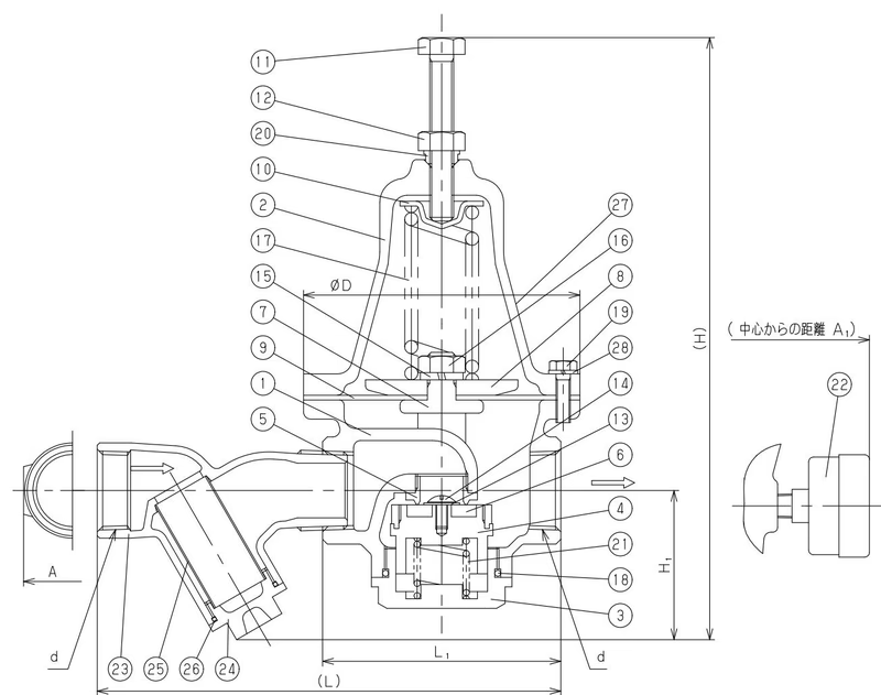
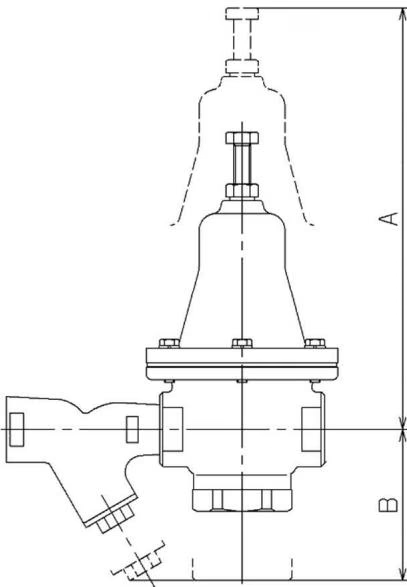
To ensure adequate maintenance space for disassembly, refer to the dimensions below.
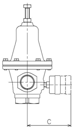
| Nominal size | A | B | C |
|---|---|---|---|
| 15A | 245 | 105 | 120 |
| 20A | 270 | 110 | 125 |
| 25A | 290 | 135 | 135 |
| 32A | 340 | 160 | 140 |
| 40A | 420 | 175 | 160 |
| 50A | 480 | 215 | 170 |
Values are in mm. The factory-installed plug at the pressure gauge joint is only for an airtightness test. Replace it with the included pressure gauge.
WARNING
In case installing a safety relief valve as a safety device at the outlet side, joint the relief pipe at the outlet of the safety relief valve and guide it to a safe place where fluid can relieve out. The set pressure of the safety relief valve must be higher than the set pressure of the pressure reducing valve plus 10%.
TIP
The GD-24 pressure reducing valve is set at 0.1 MPa at the factory. Change the set pressure as appropriate.
WARNING
Completely discharge internal pressure from the valves, lines, and equipment, and cool the valve down before disassembly and inspection to prevent burns or injury.
Many faults in the pressure reducing valve are due to foreign materials. Check for clogged strainers (which decrease secondary pressure) and leakage from the by-pass stop valve (which increases secondary pressure) before troubleshooting the valve itself.
Service life depends on frequency and usage conditions. Replace the Diaphragm and O-rings approximately every 3 years.
| Problem | Cause | Countermeasure |
|---|---|---|
| Reduced pressure exceeds prescribed level | 1. Diaphragm is damaged. 2. Foreign matter is embedded in the valve/valve seat, or scratches exist. | 1. Replace the diaphragm. 2. Disassemble and remove the foreign matter. If scratches exist, replace it. |
| Pressure does not rise to the desired level | 1. Screen is clogged. 2. Pressure gauge malfunction. | 1. Disassemble and clean. 2. Replace the pressure gauge. |
| Leakage | 1. Loosen Bolt. 2. Loosen Cap. 3. Broken O-ring for cap. | 1. Tighten Bolt. 2. Tighten Cap. 3. Replace O-ring for cap. |
| Abnormal noise is heard | 1. The suspension metal is in incorrect position. | 1. Correct the position of the suspension metal. |
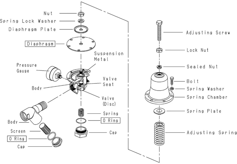 (Part names shown in boxes are consumable parts)
Yoshitake Control Valves / Pressure Reducing Valves
GP, GD, and CP series for stable pressure reduction and control in steam, water, and air systems.
Explore similar products in our catalog



