


PN25

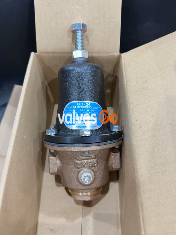
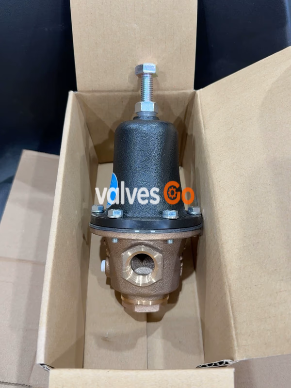
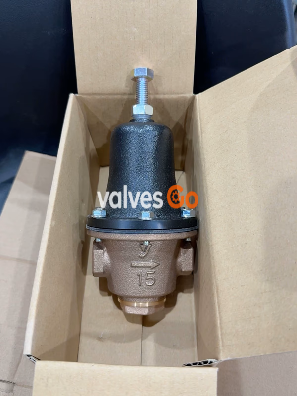
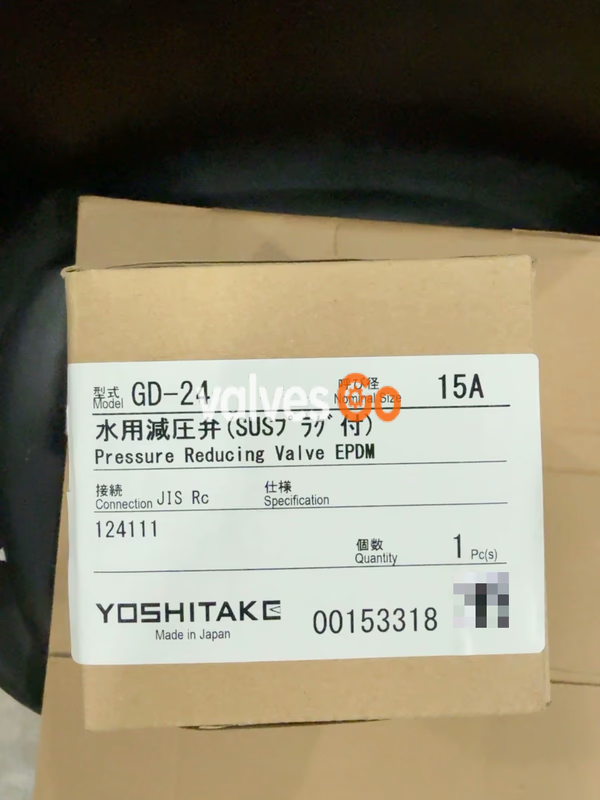
Yoshitake GD-24 direct acting water pressure reducing valve with stainless steel seat. Suitable for cold and hot water systems. 0.2-1.6 MPa inlet pressure.
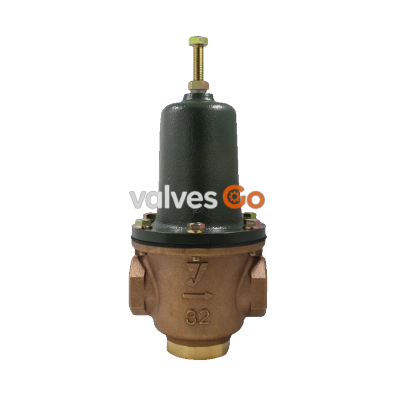
Yoshitake GD-24 water pressure reducing valve can be used as a pressure control unit in water supply systems of general residential housing, high-rise buildings, industrial plant, and factory equipment. It can also be used to provide stable water pressure in high-rise apartment units, and for hilly districts where each house requires an individual water supply system. Trouble-free flow control solutions are achieved through the use of a stainless steel valve seat and a suspension type clamp in the drive mechanism.
Options
Pressure gauge connection port is JIS Rc 1/8.
| Model | GD-24 |
|---|---|
| Application | Cold and hot water, Flushing water |
| Inlet pressure | 0.2-1.6 MPa |
| Reduced pressure | 0.05-0.55 MPa |
| Minimum differential pressure | 0.05 MPa |
| Maximum pressure reduction ratio | 10:1 |
| Application temperature | 5-80°C* |
| Connection | JIS Rc screwed |
** Do not use the valve continuously at a temperature of 70°C or above (catalog notes).*
| Part | Material |
|---|---|
| Body | Cast bronze / Bronze |
| Valve disc | Urethane rubber |
| Valve seat | Stainless steel |
| Diaphragm | EPDM / NBR |
| Cap | Bronze / Brass |
| Plug | Stainless steel |
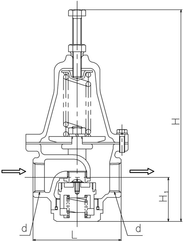
| Nominal size | d | L | H | H1 | Weight (kg) |
|---|---|---|---|---|---|
| 15A | Rc 1/2 | 80 | 193 | 41.5 | 1.8 |
| 20A | Rc 3/4 | 90 | 210 | 45 | 2.4 |
| 25A | Rc 1 | 100 | 230 | 50 | 3.3 |
| 32A (31A) | Rc 1-1/4 | 120 | 265 | 60 | 4.7 |
| 40A | Rc 1-1/2 | 150 | 315 | 62 | 8.2 |
| 50A | Rc 2 | 185 | 365 | 73 | 14.3 |
(Dimensions in mm)
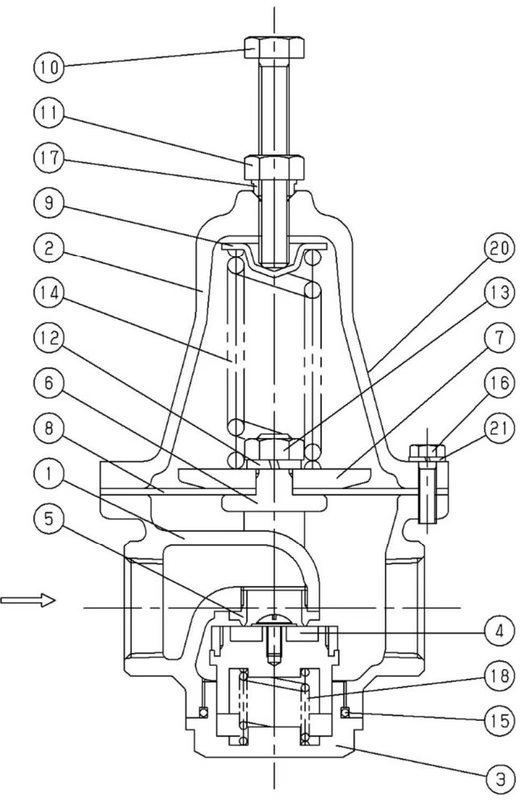
| No. | Name of parts | No. | Name of parts |
|---|---|---|---|
| 1 | Body | 12 | Washer |
| 2 | Spring Chamber | 13 | Nut |
| 3 | Cap | 14 | Adjusting Spring |
| 4 | Valve (Disc) | 15 | O-ring |
| 5 | Valve Seat | 16 | Bolt |
| 6 | Suspension Metal | 17 | Sealed Nut |
| 7 | Diaphragm Shell | 18 | Spring |
| 8 | Diaphragm | 19 | Plug |
| 9 | Spring Plate | 20 | Label |
| 10 | Adjusting Screw | 21 | Spring Washer |
| 11 | Lock Nut |
Turning the adjusting screw (10) to compress the adjusting spring (14) and the load of adjusting spring is introduced to the diaphragm (8) and suspension metal (6) to open the valve (4). Then, the fluids begin to flow from the inlet side through the upper side of the valve. The reduced pressure is led to the diaphragm to be balanced with the adjusting spring load, and control the valve travel to maintain the reduced pressure.
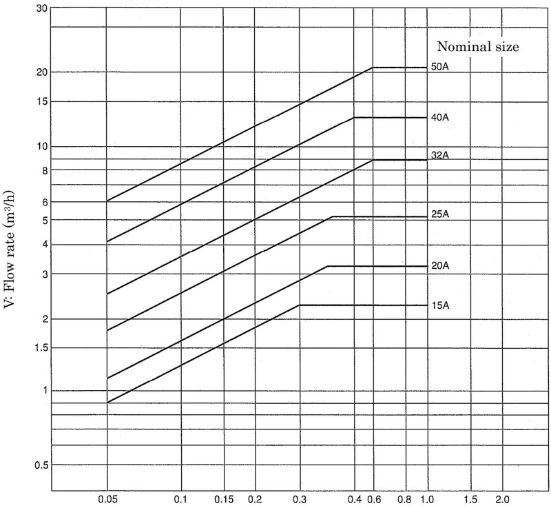 ΔP: Inlet/reduced pressure differential (MPa)
Cv Value:
| Nominal size | 15A | 20A | 25A | 32A | 40A | 50A |
|---|---|---|---|---|---|---|
| Cv value | 1.5 | 1.9 | 3.0 | 4.0 | 7.0 | 10.0 |
Flow Rate Characteristics Chart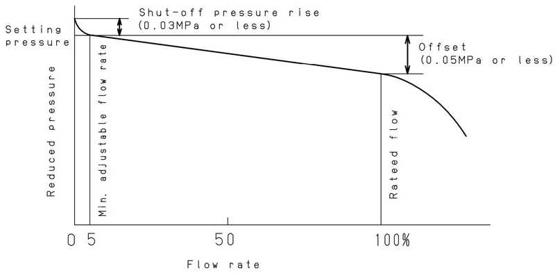
Pressure Characteristics Chart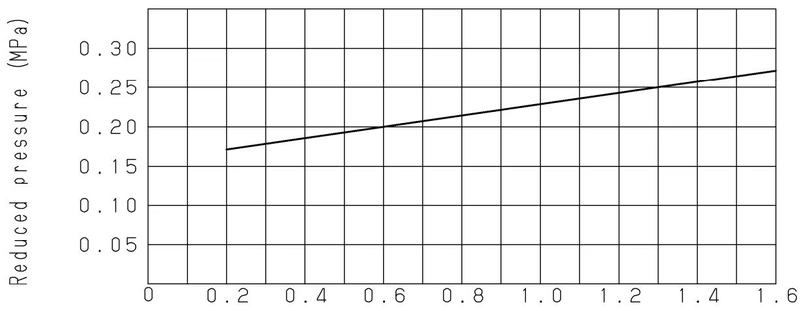 This chart shows variation in reduced pressure when the inlet pressure of 0.6 MPa is changed between 0.2 MPa and 1.6 MPa while the reduced pressure is set at 0.2 MPa.
Piping Example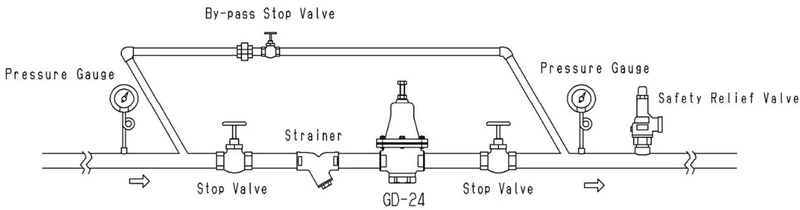
Installation Warnings & Cautions
Maintenance Space Secure the necessary maintenance space at the installation site of the pressure reducing valve. 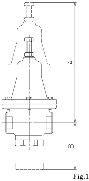
| Nominal size | A | B |
|---|---|---|
| 15A | 245 | 105 |
| 20A | 270 | 115 |
| 25A | 290 | 130 |
| 32A | 340 | 145 |
| 40A | 420 | 150 |
| 50A | 480 | 165 |
Operating Cautions
GD-24 pressure reducing valve is set at 0.1MPa at the factory. Change the set pressure as appropriate:
Maintenance Precautions
Completely discharge internal pressure from the valves, lines, and equipment, and cool the valve down to a level where you can touch it with bare hands before disassembly and inspection.
Consumable parts and replacement period:
Troubleshooting:
| Problem | Cause | Countermeasure |
|---|---|---|
| Reduced pressure exceeds prescribed level | 1. Diaphragm is damaged. 2. Foreign matter is embedded in the valve and/or valve seat, or scratches exist. | 1. Replace the diaphragm. 2. Disassemble and remove foreign matter. If scratches exist, replace it. |
| Pressure does not rise to the desired level | 1. Strainer is clogged. 2. Pressure gauge malfunction. | 1. Disassemble and clean. 2. Replace the pressure gauge. |
| Leakage | 1. Loosen Bolt (16). 2. Loosen Cap (3). 3. Broken O-ring (15) for cap. | 1. Tighten Bolt (16). 2. Tighten Cap (3). 3. Replace O-ring (15) for cap. |
| Abnormal noise is heard | The suspension metal (6) is in incorrect position. | Correct the position of the suspension metal (6). |
Exploded Drawing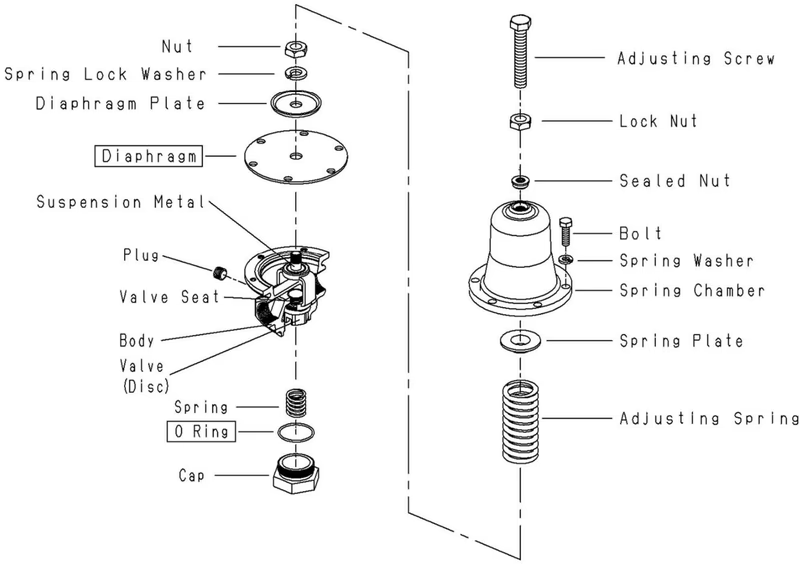
Yoshitake Control Valves / Pressure Reducing Valves
GP, GD, and CP series for stable pressure reduction and control in steam, water, and air systems.
Explore similar products in our catalog



