

PN16

Burkert 332213 (Type 8640) is an 8-bank pneumatic valve block with 19 mm station width, 3/2-way valve function, G 1/4 pressure ports, push-in D6 bottom working ports, and DIN-rail mounting for 2 to 10 bar operation.
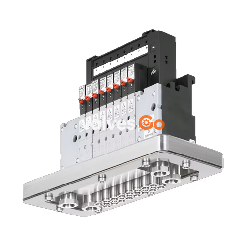
BURKERT 332213 Type 8640 is an 8-bank modular pneumatic valve block configured with a 19 mm station width per valve slot. The assembly combines modular pneumatic base rails with Type 5470 pilot-operated solenoid valves to control neutral compressed air lines across an operating pressure range of 2.0 bar to 10.0 bar. Each valve position provides a 3/2-way valve function with pneumatic working ports directed downward through integrated D6 push-in couplings, while primary pressure supply and exhaust are routed through G 1/4 ports on the manifold end modules.
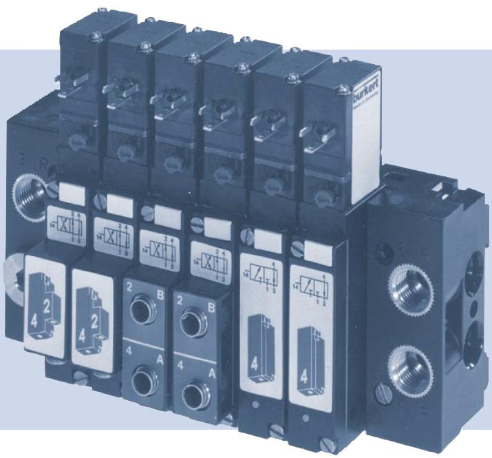
Individual valve actuation on this unit is arranged via single-wiring tag connectors conforming to DIN EN 175301-803 Form C, avoiding internal fieldbus communications. Built from polyamide (PA) bodies with NBR seals, the valve block installs onto standard DIN mounting rails EN 50022 (35 x 7.5 mm or 35 x 15 mm) inside electrical and pneumatic control cabinets, providing IP20 housing protection in base configuration and IP65 protection when fitted with Type 2516 industrial cable plugs.
| Specification Parameter | Value / Characteristic |
|---|---|
| Product Type | Type 8640 modular valve block |
| Article Number (SKU) | 332213 |
| Station Width | 19 mm per valve slot |
| Number of Valve Stations | 8-bank (8 valve slots) |
| Valve Construction | Type 5470 with Type 6106 rocker pilot valve |
| Nominal Diameter (Orifice) | DN 4.0 mm |
| Flow Rate QNn (Air) | Approx. 300 l/min (measured at +20 °C, 6 bar inlet pressure, 1 bar pressure drop) |
| Operating Pressure Range | 2.0 bar to 10.0 bar (0.2 MPa to 1.0 MPa) |
| Required Pilot Pressure | 2.0 bar to 10.0 bar (at least 70% of operating pressure) |
| Differential Pressure (Port 1 to 3) | Minimum 2.0 bar |
| Medium Temperature | 0 °C to +50 °C (operation below 0 °C restricted to dried air) |
| Ambient Temperature | 0 °C to +55 °C |
| Operating Medium | Lubricated or unlubricated filtered compressed air (≤ 10 µm, 5 µm recommended), neutral gases |
| Compressed Air Quality | ISO 8573-1:2010, Class 7.4.4 |
| Body / Module Material | Polyamide (PA) |
| Seal Material | NBR |
| Pressure Supply Port 1 (P) | G 1/4 female thread |
| Exhaust Port 3 (R) | G 1/4 female thread |
| Working Ports 2 and 4 | Push-in coupling for D6 mm tubing, bottom exit position |
| Operating Voltage | 24 V DC (±10% voltage tolerance) |
| Duty Cycle | Continuous operation (100% ED) |
| Electrical Connection | Single wiring: DIN EN 175301-803 Form C (suitable for Type 2516 cable plug) |
| Degree of Protection | IP20 (IP65 with correctly assembled Type 2516 cable plug) |
| Mounting Type | DIN rail installation (EN 50022 35 x 7.5 / 35 x 15) or wall screw mounting |
Each valve slot on the 19 mm manifold is equipped with a Type 5470 pneumatic valve driven by an integrated Type 6106 rocker solenoid pilot. The pilot armature features a tilting bearing that rocks within the pilot body without sliding friction, eliminating mechanical wear and the need for basic lubrication.
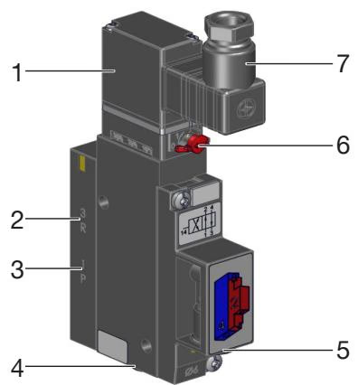
| Item | Designation | Functional Description |
|---|---|---|
| 1 | Pilot valve Type 6106 | Rocker pilot actuator with tilting bearing armature |
| 2 | Exhaust port 3 | Common exhaust duct discharging through the manifold end block |
| 3 | Pressure port 1 | Main compressed air supply channel from manifold inlet |
| 4 | Working port 4 | Pneumatic output channel (configured/plugged based on circuit function) |
| 5 | Working port 2 | Pneumatic output channel directed to bottom push-in connection |
| 6 | Manual override | Mechanical override screw for manual valve operation |
| 7 | Cable plug Type 2516 | Industrial plug conforming to DIN EN 175301-803 Form C |
Every valve station includes a mechanical manual override on the front housing. To operate the valve manually, press the manual override inward and rotate it 90° clockwise until it hits the mechanical stop. In this position, the override locks mechanically and does not reset automatically. To return to electrical operation, rotate the override counter-clockwise by 90° back to the zero position.
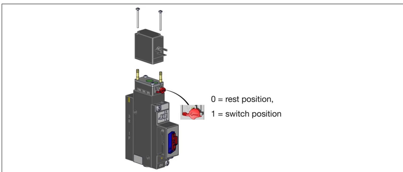
Operating Restriction
Only actuate the manual override when electrical power to the solenoid coil is switched off. Attempting manual override actuation during active electrical control can cause unintended valve cycling.
Type 5470 valves are inherently structured as 4/2-way servo-controlled valves (Circuit Function G) and can be converted into 3/2-way functions by closing either port 2 or port 4 with a dedicated stopper plug.
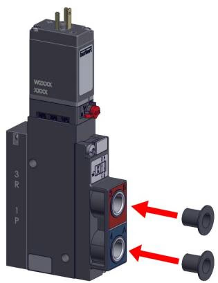
| Port 2 Configuration | Port 4 Configuration | Resulting Circuit Function | Function Description |
|---|---|---|---|
| Closed (stopper inserted) | Open | Function C (CF C) | 3/2-way valve, normally closed. In rest position, supply port 1 is closed and working port 4 exhausts to port 3. |
| Open | Closed (stopper inserted) | Function D (CF D) | 3/2-way valve, normally open. In rest position, supply port 1 connects to working port 2 and exhaust port 3 is closed. |
| Open | Open | Function G (CF G) | 4/2-way valve. In rest position, port 1 connects to port 2, and port 4 exhausts through port 3. |
The 8-bank valve block consists of modular pneumatic base modules snapped together between a left-hand and a right-hand connection module. Latch hooks and tabs join the individual sections into a rigid pneumatic assembly.
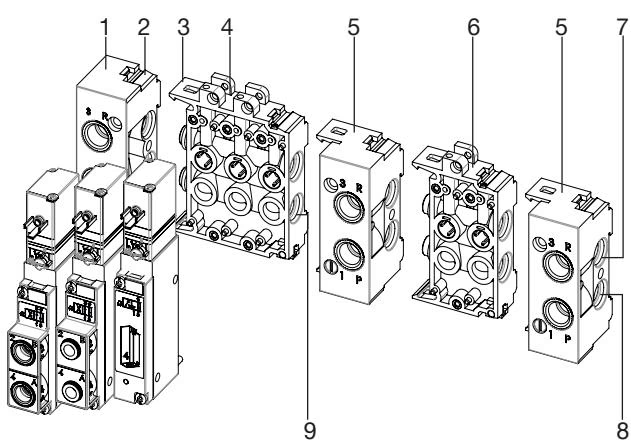
Assembly follows a fixed mechanical sequence:
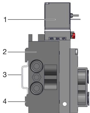
The complete 8-bank block mounts onto standard symmetrical DIN rails EN 50022 (35 x 7.5 mm or 35 x 15 mm). Hook the upper groove of the manifold clamping bracket onto the top edge of the rail, press the block downward until the lower clamping elements engage the rail profile, and tighten the clamping screws securely. Alternatively, mount the block directly against an enclosure mounting plate using M4 screws.
| Connection Port Size | Port Function | Recommended Torque | Maximum Permissible Torque |
|---|---|---|---|
| G 1/4 | Supply channel 1 (P), exhaust channel 3 (R) | 4.0 Nm to 7.0 Nm | 20.0 Nm |
| G 1/8 | Alternative port connections / valve outlets | 3.0 Nm to 6.0 Nm | 7.0 Nm |
| Valve body to base rail | M2 / M3 module mounting screws | 0.6 ±0.1 Nm | 0.7 Nm |
| Solenoid re-orientation screws | Pilot coil fastening screws M2 | Step 1: 0.1 ±0.05 Nm; Step 2: 0.2 ±0.05 Nm | 0.25 Nm |
| Cable plug center screw | Type 2516 fastening screw | 0.3 Nm | 0.3 Nm |
Mechanical Stress Caution
Never use the solenoid coil or pilot housing as a lever arm when threading fittings or silencers into the manifold ports. Do not use pipe wrenches across the valve plastic bodies.
The supply air line connects to Port 1 (P) on the manifold end plate, while Port 3 (R) exhausts air through silencers or dedicated piping. The pilot system requires a minimum pressure difference of 2.0 bar between port 1 and port 3 to actuate the internal diaphragm seats reliably. Air lines must be blown out and cleaned prior to insertion.
Pneumatic tubing connected to the bottom D6 push-in couplings must meet the following structural specifications:
Push-in connections comply with ISO 14743:2020. Tubing must be inserted straight past the initial seal ring until firmly seated against the inner stop claws. When softer PU tubing is selected, support sleeves (ID 20099400) should be inserted inside the tube end to maintain roundness under continuous pressure.
| Tubing Outer Diameter (OD) | Polyamide (PA) Tolerance | Polyurethane (PU) Tolerance | Minimum Retaining Force (PA) | Minimum Retaining Force (PU) |
|---|---|---|---|---|
| 3 mm (1/8") | ±0.08 mm | ±0.10 mm | 60 N | 25 N |
| 4 mm (5/32") | ±0.08 mm | ±0.10 mm | 70 N | 50 N |
| 6 mm (1/4") | ±0.08 mm | ±0.10 mm | 120 N | 100 N |
| 8 mm (5/16") | ±0.08 mm | ±0.10 mm | 170 N | 150 N |
| 10 mm (3/8") | ±0.08 mm | ±0.10 mm | 250 N | 200 N |
Each solenoid coil features contacts according to DIN EN 175301-803 Form C. Single wiring cables attach via Type 2516 cable plugs. Each plug can be rotated in 180° increments to suit cabinet cable routing.
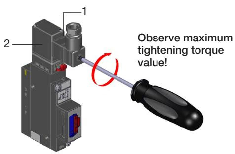
Electrical Shock Hazard
Always connect the protective grounding conductor. Verify electrical continuity between the solenoid coil grounding tab and the valve body before energizing. Protective conductor test requirements: maximum resistance 0.1 Ω at 12 V test voltage and 1 A test current.
Ensure the flat elastomer seal between the coil face and the Type 2516 cable plug is positioned correctly before tightening the central retaining screw to 0.3 Nm. Operating coils on 24 V DC requires adherence to polarity markings on the coil body. For intermittent operation after prolonged downtime, valves should be cycled at least 1 to 2 times per day to maintain switching responsiveness.
Prior to pressurization, verify that all mechanical tube fittings are locked, manual overrides are unlocked in their zero position, and supply pressure matches the 2.0 to 10.0 bar operating window. Pressurize the valve manifold before applying control voltage to prevent pilot exhaust blow-by during pressure build-up.
| Fault Symptom | Underlying Cause | Corrective Action |
|---|---|---|
| Valve fails to switch | Control voltage absent or below tolerance (±10%) | Verify supply voltage on coil terminals against rating label (24 V DC). |
| Manual override locked in actuated position | Turn manual override counter-clockwise to zero position. | |
| Main supply pressure < 2.0 bar | Check upstream regulator and increase supply pressure to ≥ 2.0 bar. | |
| Delayed switching or continuous exhaust blow-off | Supply pressure builds too slowly or drops below 2.0 bar during actuation | Provide adequate supply volume; verify differential pressure between port 1 and 3 is ≥ 2.0 bar. |
| Valves energized prior to pneumatic pressurization | Ensure manifold reaches full pressure before switching coils. | |
| Exhaust silencers undersized, restricted, or contaminated | Clean clogged silencers or replace with high-flow expansion mufflers. | |
| Particle contamination inside pilot or main seat | Cycle valves with pulsed pressure to clear debris, or replace pilot valve unit. | |
| External air leakage between modules | Missing, pinched, or damaged O-rings between base sections | Disassemble affected module and replace intermediate seals. |
| External leakage under valve base | Defective or displaced flat seal beneath Type 5470 body | Re-seat or replace valve base seal and tighten screws to 0.6 Nm. |
Explore similar products in our catalog


