

PN16

BURKERT 20150993 (Type 8640) is a 9-bank modular pneumatic valve island with 19 mm station width, G 1/4 supply ports, D6 bottom working ports, and 2 to 10 bar operating pressure.
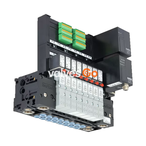
BURKERT 20150993 (Type 8640) is a 9-bank modular pneumatic valve island designed for pilot control of compressed air and neutral gases. Built with a 19 mm station width architecture, this preconfigured assembly integrates 9 valve positions on modular pneumatic base rails. It utilizes a central G 1/4 pressure supply port (1/P), bottom-facing D6 push-in working connections (2/B and 4/A), and operates within a nominal pressure span of 2.00 bar to 10.00 bar across fluid temperatures from 0 °C to +50 °C. The unit is wired individually without an internal serial bus communication module, providing IP20 protection under DIN-rail mounting conditions.

Type 8640 valve islands integrate Type 5470 solenoid valves mounted to pneumatic base rails (such as Type MP05). Each station incorporates a Type 6106 flipper pilot valve, a main valve body equipped with diaphragm and seat seals, connection interfaces, and an integrated mechanical manual override.

| Item | Designation |
|---|---|
| 1 | Pilot valve Type 6106 |
| 2 | Exhaust port 3 (R) |
| 3 | Pressure port 1 (P) |
| 4 | Working port 4 (A) |
| 5 | Working port 2 (B) |
| 6 | Manual override |
| 7 | Cable plug Type 2506 / 2516 interface |
Pneumatic connection channels follow standardized numerical designations across the manifold:
| Connection Number | Standard Designation | Manifold Function |
|---|---|---|
| 1 | Pressure port (P) | Primary pneumatic pressure supply channel |
| 2 and 4 | Working ports (B and A) | Working pneumatic outlets to actuators (D6 bottom ports) |
| 3 | Exhaust port (R) | Primary pneumatic exhaust collector channel |
Each valve station is equipped with a mechanical manual override on the pilot body to permit manual actuation during setup or electrical power interruptions.
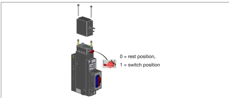
To lock the valve manually, press the manual override downward and rotate it 90° clockwise until it hits the mechanical stop. The override locks in this position and does not reset automatically. For automated electrical operation, return the manual override to its de-energized zero position.
WARNING
Actuate the manual override only when electrical control power is switched off.
Type 5470 valves on Type 8640 manifolds support circuit functions C, D, and G:
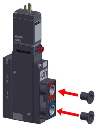
A 4/2-way valve body can be converted in the field to a 3/2-way function by sealing one of the two active working ports with an airtight stopper:
| Working Port 2 | Working Port 4 | Resulting Circuit Function |
|---|---|---|
| Closed with stopper | Open | Function C (3/2-way NC) |
| Open | Closed with stopper | Function D (3/2-way NO) |
| Technical Parameter | Specification / Limit Value |
|---|---|
| BURKERT Article Number | 20150993 |
| Island Type | 8640 modular pneumatic valve block |
| Base Width per Station | 19 mm (Add-on dimension 1) |
| Station Configuration | 9-bank (9 valve positions) |
| Supply Port 1 (P) | G 1/4 internal thread |
| Working Ports 2/4 | D6 push-in fittings, situated at the valve bottom |
| Operating Pressure Span | 2.00 bar to 10.00 bar |
| Required Pilot Pressure | 2 bar to 10 bar (minimum 70% of applied operating pressure) |
| Required Port Differential | Δp ≥ 2 bar between pressure port 1 and exhaust port 3 |
| Permissible Fluid Medium | Filtered compressed air (particle size ≤ 10 µm, unlubricated or lubricated), neutral gases (≤ 5 µm) |
| Fluid Temperature Range | 0 °C to +50 °C (operation below 0 °C restricted to dried air) |
| Ambient Temperature Range | 0 °C to +55 °C (storage range: -40 °C to +55 °C) |
| Manifold Seal Material | NBR |
| Integrated Options | Without check valves in 3(R)/5(S); without pneumatic HotSwap in 1(P) |
| Mounting Type | DIN-rail installation (EN 50022 35 x 15 or 35 x 7.5) |
| Electrical Architecture | Single wiring (without internal fieldbus communication module) |
| Enclosure Rating | IP20 |
Continuous Operation Reliability
When operating in continuous industrial service, if operation is interrupted, Bürkert recommends cycling the valves 1 to 2 switching operations per day during plant downtime to preserve seat and pilot responsiveness.
Type 8640 valve islands utilize an interlocking modular block design composed of intermediate segments and terminating connection modules.
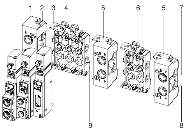
| Item | Designation |
|---|---|
| 1 | Left connection module |
| 2 | Latch tab |
| 3 | Latch hook |
| 4 | Base modules (3-fold) |
| 5 | Right connection module |
| 6 | Base modules (2-fold) |
| 7 | Exhaust channel 3(R) |
| 8 | Supply channel 1(P) |
| 9 | O-ring seals |
Prevent Seal Extrusion
Crushed or pinched O-rings and profile seals between base modules cause cross-channel internal leakage or pressure drops.
If installation clearances require an alternate coil exit orientation, the pilot solenoid can be rotated 180°:
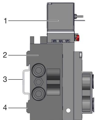
| Port Size | Circuit Designation | Recommended Torque | Maximum Torque |
|---|---|---|---|
| G 1/4 / NPT 1/4 | Port 1 (P), Port 3 (R/S) | 4 Nm to 7 Nm | 20 Nm |
| G 1/8 / NPT 1/8 | Port 1 (P), Port 3 (R/S), Outlets A/B | 3 Nm to 6 Nm | 7 Nm |
| Hose Material | Outer Diameter (OD) | Permitted Deviation |
|---|---|---|
| Polyamide (PA) | 3 mm to 10 mm | ±0.08 mm |
| Polyamide (PA) | 12 mm to 16 mm | ±0.10 mm |
| Polyurethane (PU) | 3 mm to 8 mm | ±0.10 mm |
| Polyurethane (PU) | 10 mm to 16 mm | ±0.15 mm |
| Hose Outer Diameter (OD) | 3 mm (1/8") | 4 mm (5/32") | 6 mm (1/4") | 8 mm (5/16") | 10 mm (3/8") | 12 mm (1/2") | 14 mm | 16 mm (5/8") |
|---|---|---|---|---|---|---|---|---|
| Min. Tensile Force: PA (N) | 60 | 70 | 120 | 170 | 250 | 300 | 300 | 350 |
| Min. Tensile Force: PU (N) | 25 | 50 | 100 | 150 | 200 | 200 | 250 | 300 |
Soft Tubing Installation
When using flexible polyurethane (PU) tubing subject to retention difficulties, install internal support sleeves (article ID 20099400) inside the hose end to reinforce radial holding power.
Model 20150993 utilizes single wiring directly to individual solenoid coils via Form C cable plugs (e.g. Type 2516 or DIN EN 175301-803 Form C).
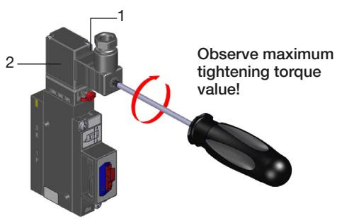
| Item | Designation |
|---|---|
| 1 | Profile flat seal |
| 2 | Cable plug (Type 2516 or DIN ISO 175301-803 Form C) |
| Fault Symptom | Probable Cause | Remedial Action |
|---|---|---|
| Valves fail to switch | Absence of operating voltage or supply voltage below tolerance | Check terminal connections; confirm that operating voltage matches coil rating within ±10%. |
| Manual override engaged in non-zero position | Return mechanical manual override to its neutral position. | |
| Insufficient pressure supply or supply flow volume restricted | Verify minimum operating pressure ≥ 2.0 bar across all feeding regulators, maintenance units, and isolation valves. | |
| Valves exhibit switching delays or continuous venting at exhaust ports | Supply pressure deficient or line volume choked | Install larger accumulator/feeder capacity; confirm pressure ≥ 2.0 bar. |
| Island not in de-energized home state during initial pressure build-up | Pressurize the pneumatic manifold before applying electrical control switching signals. | |
| Exhaust restriction or back-pressure from clogged/undersized silencers | Clean contaminated silencers or replace with larger exhaust ports/expansion mufflers. | |
| Particulate contamination inside pilot stage or spool chamber | Apply pulsed air bursts to exhaust ducts to clear debris; if seats are scored, replace the valve module. | |
| External leakage across valve blocks | Missing, displaced, or pinched inter-module O-rings | Disassemble block segments and replace damaged elastomer O-rings. |
| Base plate flat gaskets displaced or missing | Inspect sub-base seating; reinstall or replace flat seal gaskets. |
Explore similar products in our catalog


