

PN16

BURKERT 20121702 (Type 8640) is a 16-bank modular pneumatic valve island with 33 mm width, G 1/2 supply, G 1/4 ports, 3/2 valve function, 2 to 8 bar pressure range, and DIN-rail mounting.
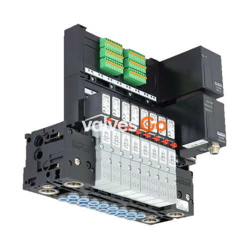
BURKERT 20121702 (Type 8640) is a 16-bank modular pneumatic valve island configured with a 33 mm station width, G 1/2 pressure supply ports, and G 1/4 working connections positioned opposite the supply side. Operating on a single-wiring electrical arrangement without internal fieldbus communication, the assembly utilizes 3/2-way valve functionality to control neutral gases and compressed air within a nominal operating pressure envelope of 2.00 bar to 8.00 bar.
Designed for integration onto standard DIN rails in control cabinets, this valve island integrates multiple sub-base modules into a centralized pneumatic distribution manifold. The pilot stages are operated by low-power solenoid pilot valves, while NBR seals and robust modular bodies ensure tight pneumatic isolation across medium operating temperatures from 0 °C to +50 °C.
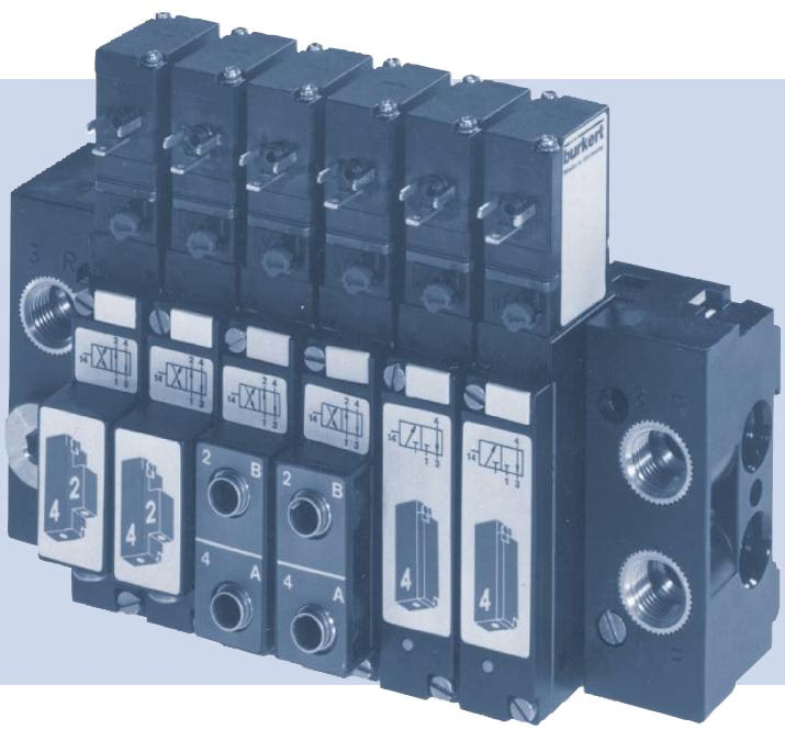
The pneumatic block integrates modular sub-bases equipped with Type 5470 solenoid valves, driven by Type 6106 pilot valves. Each valve station features internal pilot channeling, diaphragm-seat seals, integrated working ports, and manual override mechanisms.

| Item | Designation |
|---|---|
| 1 | Pilot valve Type 6106 |
| 2 | Exhaust port 3 (R) |
| 3 | Pressure port 1 (P) |
| 4 | Working port 4 (A) |
| 5 | Working port 2 (B) |
| 6 | Manual override |
| 7 | Cable plug Type 2506 / Type 2516 |
Manual operation allows commissioning and functional checks when electrical control signals are de-energized.
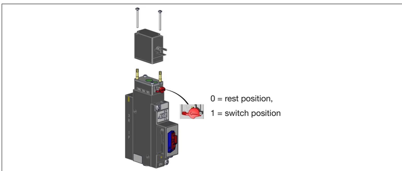
Operating the Manual Override
To activate the valve manually, press the manual override down and turn it 90° clockwise until it hits the mechanical stop. The override locks mechanically and does not reset automatically. Return it to the 0° zero position before initiating electrical operation.
All pneumatic connections on the Type 8640 island and individual valve slices follow standard numeric markings:
| Connection Number | Port Function |
|---|---|
| 1 | Pressure supply port (P) |
| 2 and 4 | Working ports (B and A) |
| 3 | Exhaust port (R) |
Depending on the internal configuration and base porting, Type 5470 valve slices support standard directional functions:
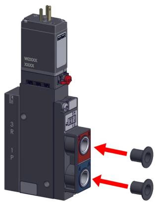
A 4/2-way valve can be converted to 3/2-way functionality by closing one of the working ports with a dedicated threaded plug or stopper:
| Port 2 | Port 4 | Resulting Circuit Function |
|---|---|---|
| Closed | Open | Function C (Normally Closed) |
| Open | Closed | Function D (Normally Open) |
| Parameter | Specification |
|---|---|
| Ident Number (Article Number) | 20121702 |
| Valve Island Type | 8640 |
| Number of Valve Stations | 16-bank |
| Station Width (Add-on dimension 1) | 33 mm |
| Valve Function | 3/2-way |
| Pressure Port 1 (P) | G 1/2 |
| Working Ports 2 (B) / 4 (A) | G 1/4 |
| Nominal Operating Pressure Range | 2.00 bar to 8.00 bar |
| Pilot Pressure Requirement | 2 bar to 10 bar (at least 70% of operating pressure) |
| Minimum Pressure Differential (Port 1 to 3) | 2 bar |
| Medium Temperature Range | 0 °C to +50 °C (operation below 0 °C restricted to dried air) |
| Ambient Temperature Range | 0 °C to +55 °C |
| Medium | Filtered compressed air (particle size max. 10 μm, lubricated or unlubricated); neutral gases (5 μm filtering) |
| Seal Material | NBR |
| Protection Class | IP20 (base unit configuration); IP65 with Type 2516 cable plug correctly fitted |
| Mounting Standard | DIN-rail installation (EN 50022: 35 x 15 or 35 x 7.5) |
| Voltage Tolerance | ±10% |
| Coil Power Rating | 2 W (standard continuous DC coil) |
| Approvals | UL Recognized cURus (pneumatic valves) |
Continuous Operation Guideline
If continuous operation is interrupted, perform a minimum of 1 to 2 switching operations per day throughout the downtime to maintain functional switching reliability.
Type 8640 valve blocks are assembled modularly by snapping base modules together between dedicated left and right connection modules.
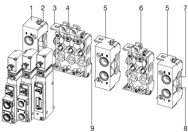
| Item | Designation |
|---|---|
| 1 | Left connection module |
| 2 | Latch tab |
| 3 | Latch hook |
| 4 | Base modules (3-fold) |
| 5 | Right connection module |
| 6 | Base modules (2-fold) |
| 7 | Exhaust channel 3 (R) |
| 8 | Supply channel 1 (P) |
| 9 | Inter-module O-ring |
Sealing Integrity
Crushed, twisted, or missing O-rings and profile seals between modular sub-bases will result in pneumatic leakage across the central channels.
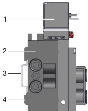
| Port Thread Size | Function / Location | Recommended Torque [Nm] | Maximum Torque [Nm] |
|---|---|---|---|
| G 1/4 / NPT 1/4 | P (Supply), R/S (Exhaust) connections | 4 to 7 | 20 |
| G 1/8 / NPT 1/8 | P, R/S connections, A/B working ports | 3 to 6 | 7 |
Pressure Hazard
Depressurize and vent all pneumatic lines before commencing installation or servicing. Loose, flapping compressed air lines can cause severe bodily injury.
When connecting pneumatic lines to push-in connectors or threaded ports, adhere to the following hose line criteria:
| Hose Material | Hose OD [mm] | Permitted Deviation OD [mm] |
|---|---|---|
| Polyamide (PA) | 3 to 10 | ±0.08 |
| Polyamide (PA) | 12 to 16 | ±0.10 |
| Polyurethane (PU) | 3 to 8 | ±0.10 |
| Polyurethane (PU) | 10 to 16 | ±0.15 |
Pneumatic push-in fittings must withstand the tensile testing values specified in DIN ISO 14743:2020 without detaching:
| Hose OD [mm] | Hose OD [in] | Min. Tensile Force PA [N] | Min. Tensile Force PU [N] |
|---|---|---|---|
| 3 | 1/8 (3.17) | 60 | 25 |
| 4 | 5/32 (4.00) | 70 | 50 |
| 6 | 1/4 (6.35) | 120 | 100 |
| 8 | 5/16 (8.00) | 170 | 150 |
| 10 | 3/8 (9.52) | 250 | 200 |
| 12 | 1/2 (12.70) | 300 | 200 |
| 14 | — | 300 | 250 |
| 16 | 5/8 (16.00) | 350 | 300 |
Hose Support Sleeves
When using softer polyurethane (PU) tubing under high operating temperatures or dynamic movements, install internal support sleeves (ID 20099400) to prevent hose collapse and maintain sealing grip.
Each solenoid valve station on the single-wired 20121702 island utilizes an industrial standard Form C connection interface.
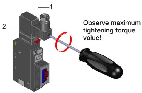
| Test Parameter | Required Test Value |
|---|---|
| Earth Contact Resistance | Maximum 0.1 Ω |
| Test Voltage | 12 V |
| Test Current | 1 A |
For bistable impulse coil variants, observe correct wiring polarity and provide a minimum pulse duration of 50 ms:
| Plug Terminal Configuration | Pilot Valve State | Function WWG Flow Path | Function WWC Flow Path |
|---|---|---|---|
| (+) on pin 2, (-) on pin 1 | Pilot valve opened | 1 → 3, 2 → 3 | 1 → 4 |
| (+) on pin 1, (-) on pin 2 | Pilot valve closed | 1 → 2, 4 → 3 | 4 → 3 |
| Fault Symptom | Probable Cause | Corrective Action |
|---|---|---|
| Valves do not switch | Operating voltage missing or below tolerance | Check wiring terminals; verify voltage corresponds to the rating on the type label. |
| Valves do not switch | Manual override engaged | Reset manual override to the zero position. |
| Valves do not switch | Insufficient supply pressure | Ensure operating pressure is at least 2 bar; check upstream pressure regulators and filters. |
| Valves switch with delay or exhaust continuously | Inadequate air volume or pressure drop | Size air supply lines adequately; verify minimum 2 bar operating pressure. |
| Valves switch with delay or exhaust continuously | Valve not in home position during pressure buildup | Apply supply pressure to the valve block before switching electrical controls. |
| Valves switch with delay or exhaust continuously | Exhaust back-pressure from clogged or undersized silencers | Clean contaminated silencers or install higher-flow silencers and expansion vessels. |
| Valves switch with delay or exhaust continuously | Contamination in pilot or main valve seat | Apply pressure pulses through exhaust ducts to dislodge dirt, or replace affected valve slice. |
| Pneumatic leaks on valve island | Damaged or missing O-rings between sub-bases | Inspect module joints; replace damaged or omitted inter-base O-rings. |
| Pneumatic leaks on valve island | Misaligned flat seal under valve body | Realign or replace flat gasket between valve body and sub-base. |
Dual Pressure and Auxiliary Air Feeding
The right connection module can be utilized in specialized layouts as an intermediate pressure separator, allowing two distinct operating pressure zones on a single island, or as an auxiliary air inlet for high-flow installations. If required, pierce the pre-punched lateral knockout ports on channels 1 and 3.
Explore similar products in our catalog


