


PN25

The Yoshitake GP-1000HEN is a pilot-operated pressure reducing valve for steam applications. Featuring an EN PN25 flanged connection, a ductile cast iron body, and a 20:1 max reduction ratio.
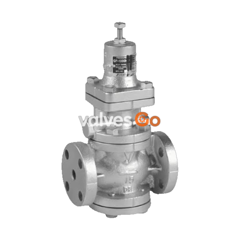
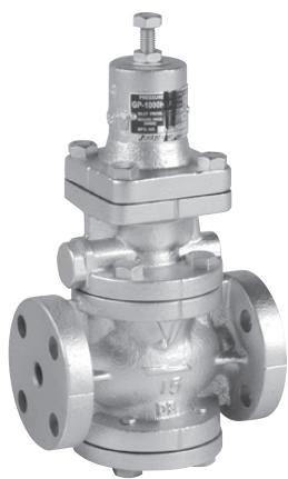
Yoshitake GP-1000HEN is a pilot-operated pressure reducing valve designed for steam applications. It features a ductile cast iron body and stainless steel internals, offering precise control over pressure fluctuations and flow rate changes.
| Model | GP-1000HEN / GP-1000H |
|---|---|
| Application | Steam |
| Inlet pressure | 0.1-1.6 MPa |
| Reduced pressure | (A) 0.05-0.9 MPa (B) 0.9-1.4 MPa 90% or less of inlet pressure (gauge pressure) |
| Minimum differential pressure | 0.05 MPa |
| Maximum pressure reduction ratio | 20:1 |
| Maximum temperature | 220°C |
| Valve seat leakage | 0.01% or less of rated flow rate |
| Material: Body | Ductile cast iron |
| Material: Main valve, valve seat | Stainless steel |
| Material: Pilot valve, pilot valve seat | Stainless steel |
| Material: Piston, cylinder | Stainless steel |
| Material: Diaphragm | Stainless steel |
| Connection | EN PN25 flanged |
INFO
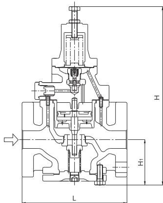
| Nominal size | L (GP-1000HEN) | L (GP-1000H) | H (GP-1000HEN) | H (GP-1000H) | H1 | Weight (GP-1000HEN) | Weight (GP-1000H) |
|---|---|---|---|---|---|---|---|
| 15A | 150 | 150(-) | 291 | 285 | 64 | 8.0 | 8.0(-) |
| 20A | 150 | 155(-) | 291 | 285 | 64 | 8.5 | 8.5(-) |
| 25A | 160 | 160 (160) | 300 | 300 | 67 | 10.0 | 10.0 (10.0) |
| 32A | 180 | 190 (180) | 333 | 323 | 82 | 14.0 | 14.0 (14.0) |
| 40A | 200 | 190 (200) | 333 | 323 | 82 | 15.5 | 14.5 (15.5) |
| 50A | 230 | 220 (230) | 353 | 347 | 93 | 21.0 | 20.0 (21.0) |
INFO
The values in parentheses are the dimensions of ASME Class 300 flanged.
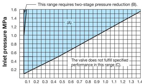
Find the intersection point of the inlet and reduced pressures. If the intersection point is within range (A) in the chart, the pressures are controllable with a single pressure reducing valve. They can be controlled by two-stage pressure reduction if the intersection point is within range (B). The valve does not fulfill specified performance in range (C).
Pressure Characteristic Chart
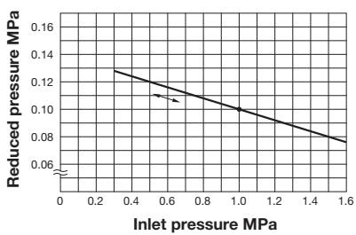
This chart shows variation in reduced pressure when the inlet pressure of 1.0 MPa is changed between 0.3 MPa and 1.6 MPa while the reduced pressure is set at 0.1 MPa.
Flow Characteristic Chart
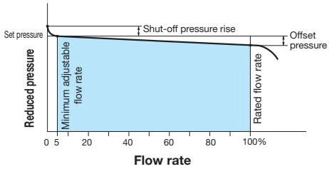
Table of rated Cv values (Cv value when the correction factor C = 1)
| Nominal size | 15A | 20A | 25A | 32A | 40A | 50A | 65A | 80A | 100A |
|---|---|---|---|---|---|---|---|---|---|
| Cv values | 1 | 2.3 | 4 | 6.5 | 9 | 16 | 25 | 36 | 64 |
Note
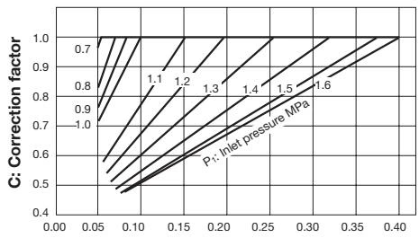
When the reduced pressure is within either of the ranges shown below, calculate the corrected Cv value by multiplying the rated Cv value by the correction factor C obtained from Fig. 1.
Fig. 1: Corrected Cv value
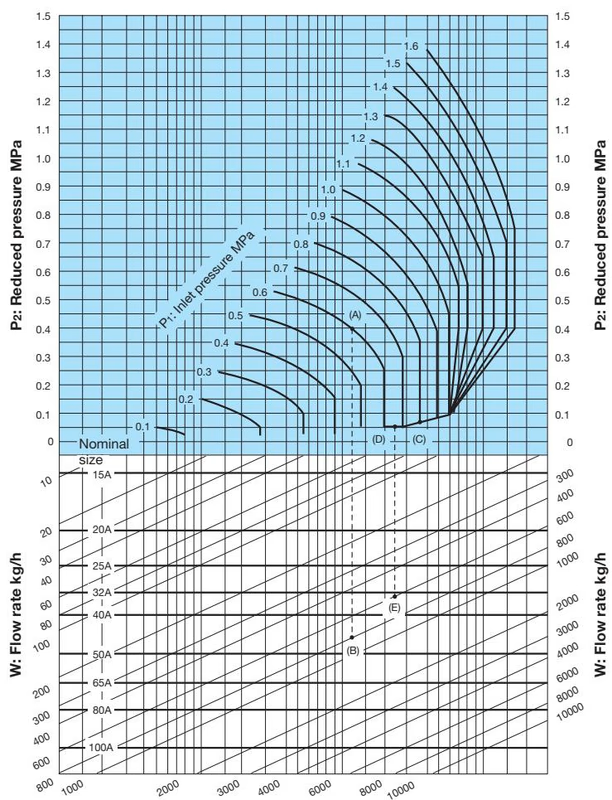
When selecting the nominal diameter of a pressure reducing valve with an inlet pressure (P1) of 0.8 MPa, reduced pressure (P2) of 0.05 MPa, and steam flow rate of 600 kg/h, first find the intersection point (C) of the inlet pressure 0.8 MPa and the diagonal line. Then, move left from this point to find the intersection point (D) with the reduced pressure of 0.05 MPa. From point (D), move vertically downward to find the intersection point (E) with the flow rate of 600 kg/h. Since point (E) lies between the nominal diameters 32A and 40A, select the larger diameter, 40A.
TIP
Set the safety factor at 80 to 90%.
Yoshitake Control Valves / Pressure Reducing Valves
GP, GD, and CP series for stable pressure reduction and control in steam, water, and air systems.
Explore similar products in our catalog



