


PN25

Yoshitake GDK-2000 direct acting, remote operation steam pressure reducing valve. Features ductile cast iron body, external sensing, and a 10:1 reduction ratio.
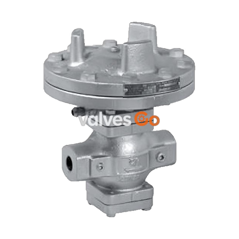
Yoshitake GDK-2000 is a direct acting pressure reducing valve designed for steam applications. It features a simple but robust structure with fewer moving parts. The spherical main valve offers great sealability, providing a significant reduction of valve seat leakage compliant with ANSI Class IV. A large-size diaphragm ensures a high Cv value and distinguished controllability against load fluctuations. Furthermore, its remote operation capability makes pressure adjustment easy and provides a wide pressure setting range.
| Specification | Value |
|---|---|
| Application | Steam |
| Reduced pressure sensing method | External sensing |
| Inlet pressure | 0.1-2.0 MPa / 0.1-1.0 MPa |
| Reduced pressure | 0.05-1.4 MPa / 0.05-0.9 MPa (90% or less of inlet pressure) |
| Operation air pressure | Refer to the loading air pressure-set pressure chart |
| Minimum differential pressure | 0.05 MPa |
| Maximum pressure reduction ratio | 10:1 |
| Maximum temperature | 220℃ |
| Valve seat leakage | 0.01% or less of rated flow |
| Material (Body) | Ductile cast iron |
| Material (Valve) | Stainless steel |
| Material (Valve seat) | Stainless steel |
| Material (Diaphragm) | Stainless steel |
| Reduced pressure sensing pipe | Copper pipe φ 8-2 m |
| Connection | JIS Rc screwed, JIS 20K RF flanged, JIS 10K FF flanged |
INFO
External sensing is standard. When installing the pressure reducing valve, be sure to connect the provided sensing pipe and joint. Unless the sensing pipe is connected, the valve will not operate. Available with ASME or EN flanged.
| Nominal size | d | L | H1 | H | A | Weight (kg) |
|---|---|---|---|---|---|---|
| 15A | Rc 1/2 | 150 | 74 | 244 | 200 | 12.4 |
| 20A | Rc 3/4 | 150 | 74 | 244 | 200 | 12.4 |
| 25A | Rc 1 | 160 | 76 | 251 | 226 | 16.4 |
| 32A | Rc 1-1/4 | 180 | 90 | 282 | 226 | 19.9 |
| 40A | Rc 1-1/2 | 180 | 90 | 282 | 226 | 19.9 |
| 50A | Rc 2 | 230 | 103 | 319 | 276 | 30.5 |
INFO
Available with NPT connection.
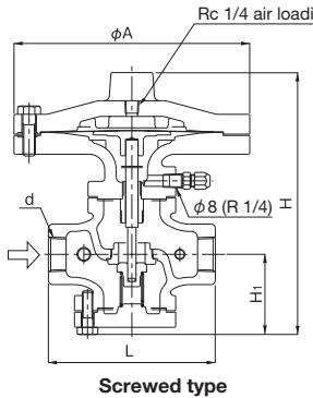
| Nominal size | L | H1 | H | A | Weight (kg) |
|---|---|---|---|---|---|
| 15A | 146 (142) | 74 | 244 | 200 | 13.9 (13.7) |
| 20A | 146 (142) | 74 | 244 | 200 | 14.4 (14.2) |
| 25A | 156 (152) | 76 | 251 | 226 | 19.2 (18.8) |
| 32A | 176 (172) | 90 | 282 | 226 | 22.4 (22.0) |
| 40A | 196 (192) | 90 | 282 | 226 | 22.9 (22.5) |
| 50A | 222 (218) | 103 | 319 | 276 | 33.5 (33.5) |
| 65A | 282 (278) | 122 | 373 | 352 | 61.8 (61.5) |
| 80A | 302 (294) | 135 | 399 | 352 | 69.1 (66.9) |
INFO
The values in parentheses are the dimensions and weights of JIS 10K FF flanged. Please contact us about other specifications.

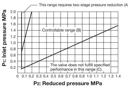
Please refer to the selection chart to select the most appropriate pressure reducing valve. Find the point of intersection of inlet pressure (P1) and reduced pressure (P2). When the point of intersection is within range (A), reduce pressure in two stages. When within range (B), controllable range. When within range (C), maximum performance cannot be obtained. When reducing pressure in two stages, maximize the distance between the valves (at least 3 m).
When selecting a nominal size, set the flow rate at 80 to 90% of the rated flow rate, allowing for the pressure loss and heat loss of the stop valve, strainer, etc. to be used before or after the pressure reducing valve. To enable the pressure reducing valve to show a maximum flow characteristic, do not select a small piping diameter, as a countermeasure against the effect of piping resistance.
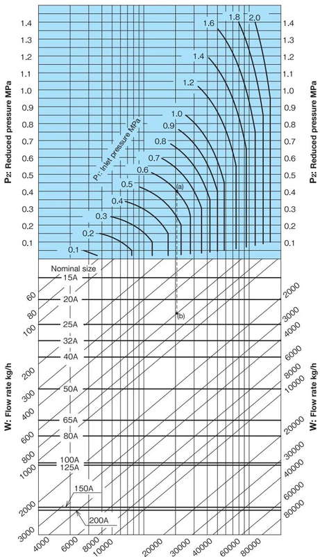
When selecting the nominal size of a pressure reducing valve whose inlet pressure (P1), reduced pressure (P2), and flow rate are 0.6 MPa, 0.4 MPa, and 600 kg/h, respectively, first find intersection point (a) of the inlet pressure of 0.6 MPa and the reduced pressure of 0.4 MPa. Trace down vertically from this intersection point to find intersection point (b) with the flow rate of 600 kg/h. Since intersection point (b) lies between nominal sizes 20A and 25A, select the larger one, 25A. Set the safety factor at 80 to 90%.
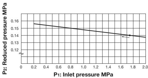
This chart shows variation in reduced pressure when the inlet pressure of 1.75 MPa is changed between 0.2 MPa and 2.0 MPa while the reduced pressure is set at 0.14 MPa.
Basically, the set pressure to the loading air pressure is as shown in the chart above. The set pressure is slightly different depending on the working conditions. For the actual use, adjust loading air pressure suitable for the necessary set pressure.
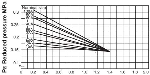
This chart shows variation in reduced pressure when the inlet pressure of 1.4 MPa is changed between 0.2 MPa and 1.4 MPa while the reduced pressure is set at 0.14 MPa.
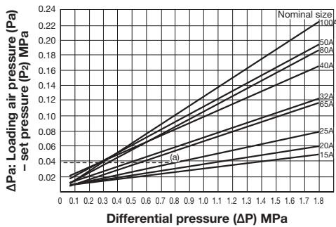
How to read the chart (GDK-2000)
When the nominal size is 25A, the inlet pressure (P1) is 1.0 MPa, and the reduced pressure (P2) is 0.2 MPa, the loading air pressure is calculated as follows: Trace up vertically from the differential pressure (∆P) before and after the pressure reducing valve (1.0 MPa – 0.2 MPa = 0.8 MPa) to find intersection point (a) with the nominal size of 25A. Calculate ΔPa [loading air pressure (Pa) – set pressure (P2)] = 0.037 MPa by horizontally tracing to the left from intersection point (a). Thus, the loading air pressure is: (Pa) = ∆Pa + P2 = 0.037 + 0.2 = 0.237 MPa.
Yoshitake Control Valves / Pressure Reducing Valves
GP, GD, and CP series for stable pressure reduction and control in steam, water, and air systems.
Explore similar products in our catalog



