


PN25

Yoshitake GD-400SS direct-acting pressure reducing valve in cast stainless steel for air and nitrogen gas. Features a 2.5-400 kPa inlet range and external sensing.
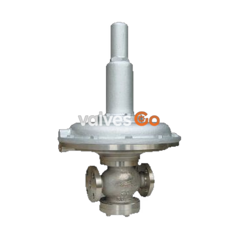
The Yoshitake GD-400SS is a direct-acting pressure reducing valve constructed from cast stainless steel (SCS14), designed for air and nitrogen gas applications. It maintains a constant reduced pressure without being affected by inlet pressure variations, utilizing a large pressure sensing diaphragm for accurate set pressure control. The valve features a simple structure for easy maintenance and supports a high maximum pressure reduction ratio of 400:1.
| Model | GD-400SS |
|---|---|
| Nominal size | 15-50A |
| Application | Air, Nitrogen gas *1 |
| Inlet pressure | 2.5-400 kPa |
| Reduced pressure | (A) 0.5-1.4 kPa (B) 1.2-3.3 kPa (C) 3.0-8.0 kPa (D) 7.0-20 kPa |
| Working temperature | 5-60℃ |
| Minimum differential pressure | 2.0 kPa |
| Maximum pressure reduction ratio | 400:1 |
| Reduced pressure detection method | External sensing *2 |
| Minimum adjustable flow rate | 15-25A: 1.2 m³/h (standard condition) 32-50A: 10.0 m³/h (standard condition) |
| Material: Body | Cast stainless steel (SCS14) |
| Material: Valve / Valve seat / Spindle | Stainless steel |
| Material: Disc / Diaphragm | NBR *3 |
| Connection | JIS 10K FF Flanged |
| Nominal size | L | H1 | H | Weight |
|---|---|---|---|---|
| 15A | 166 | 86 | 526 | 32.0 kg |
| 20A | 170 | 86 | 526 | 32.0 kg |
| 25A | 170 | 86 | 526 | 33.0 kg |
| 32A | 180 | 96 | 561 | 34.0 kg |
| 40A | 180 | 96 | 561 | 34.0 kg |
| 50A | 180 | 101 | 561 | 35.0 kg |
(Note: Dimensions are in mm. Weights shown are for the GD-400SS type).
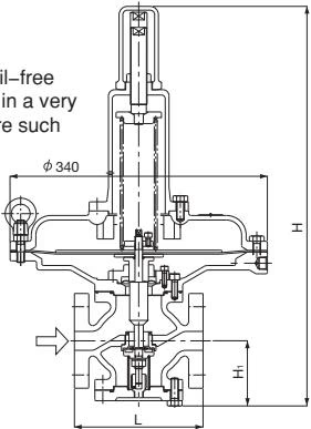 15A-25A
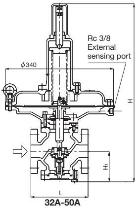 32A-50A
Flow Characteristic Chart
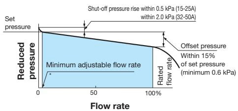 15-25A: 1.2 m³/h (standard condition) / 32-50A: 10.0 m³/h (standard condition)
Pressure Characteristic Chart
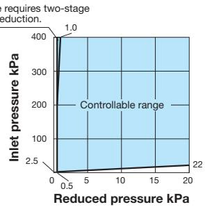
Specifications Chart
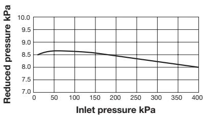 This chart shows variation in reduced pressure when the inlet pressure of 400 kPa is changed to 10 kPa while the reduced pressure is set at 8.0 kPa.
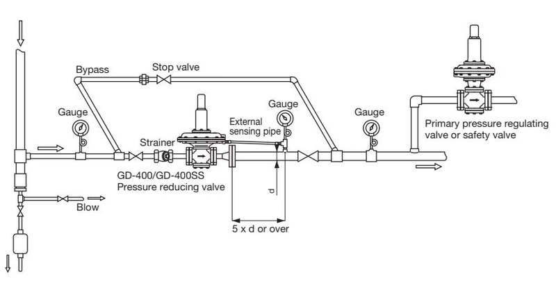
Precautions
If pressure beyond the specified airtest pressure is applied, internal parts may be damaged.
| Airtight test | Airtight test pressure | |
|---|---|---|
| Inlet pressure | 400 kPa or less | |
| Reduced pressure | Spring range A | 1.8 kPa or less |
| Reduced pressure | Spring range B | 4.2 kPa or less |
| Reduced pressure | Spring range C | 10 kPa or less |
| Reduced pressure | Spring range D | 25 kPa or less |
When the inlet pressure is between 2.5 kPa and 200 kPa (Fluid: 20°C Air)
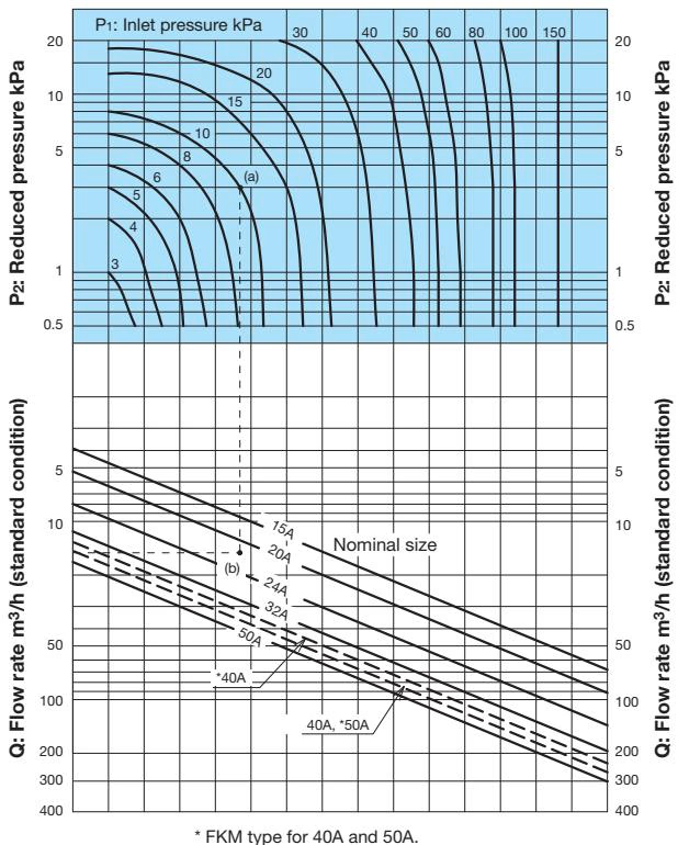
Selection Example
When selecting the nominal size of a pressure reducing valve whose inlet pressure (P1), reduced pressure (P2), and flow rate are 10 kPa, 3 kPa, and 15 m³/h (standard condition), respectively: First find intersection point (a) of the inlet pressure of 10 kPa and the reduced pressure of 3 kPa. Trace down vertically from this intersection point to find intersection point (b) with the flow rate of 15 m³/h (standard condition). Since intersection point (b) lies between nominal sizes 20A and 25A, select the larger one, 25A.
*Set the safety factor at 80 to 90%.
When the inlet pressure is between 200 kPa and 400 kPa
| Nominal size | Inlet pressure (kPa) | Rated flow rate (m³/h [standard condition]) | Rated flow rate (m³/h [standard condition]) |
|---|---|---|---|
| Reduced pressure: 0.5-4 kPa | Reduced pressure: 4-20 kPa | ||
| 15A | 200-400 | 60 | 60 |
| 20A | 200-300 | 90 | 90 |
| 20A | 300-400 | 90 | 120 |
| 25A | 200-300 | 120 | 120 |
| 25A | 300-400 | 120 | 150 |
| 25A | 400 | 120 | 190 |
| 32A | 200-300 | 200 | 250 |
| 32A | 300-400 | 200 | 300 |
| 40A | 200-300 | 250 | 275 |
| 40A | 300-400 | 250 | 325 |
| 50A | 200-300 | 325 [275] | 375 [325] |
| 50A | 300-400 | 325 [275] | 425 [375] |
(Note: The values in brackets [] are the flow rates for the FKM type).
Yoshitake Control Valves / Pressure Reducing Valves
GP, GD, and CP series for stable pressure reduction and control in steam, water, and air systems.
Explore similar products in our catalog



