


PN25

Yoshitake GD-28S-NE, GD-29S-NE pressure reducing valves for cold and hot water. SCS13 body, inlet pressure up to 2.0 MPa, and reduced pressure 0.20-0.70 MPa.
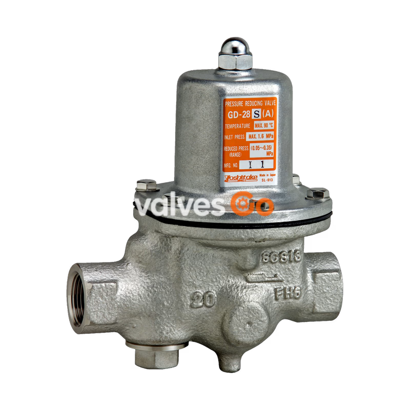
Yoshitake GD-28S-NE and GD-29S-NE are pressure reducing valves designed for cold and hot water applications. They feature an SCS13 body, FKM valve disc, and EPDM diaphragm, ensuring reliable performance up to a maximum temperature of 90°C and an inlet pressure of up to 2.0 MPa. The series offers reduced pressure ranges from 0.20 to 0.70 MPa.
The GD-28S-NE is available in nominal sizes from 20A to 50A with JIS Rc screwed connections, while the GD-29S-NE covers sizes from 20A to 100A with JIS 20K RF flanged connections. Models in sizes 20A to 50A incorporate a 40 mesh strainer.
| Model | GD-28S-NE | GD-29S-NE |
|---|---|---|
| Nominal size | 20A-50A | 20A-100A |
| Application | Cold and hot water | Cold and hot water |
| Inlet pressure | 2.0 MPa or less | 2.0 MPa or less |
| Reduced pressure A | 0.20 - 0.35 MPa | 0.20 - 0.35 MPa |
| Reduced pressure B | 0.30 - 0.70 MPa | 0.30 - 0.70 MPa |
| Min. differential pressure | 0.05 MPa | 0.05 MPa |
| Max. temperature | 90°C | 90°C |
| Body | SCS13 | SCS13 |
| Valve seat | SCS13 | SCS13 |
| Valve disc | FKM | FKM |
| Diaphragm | EPDM | EPDM |
| Connection | JIS Rc screwed | JIS 20K RF flanged |
INFO
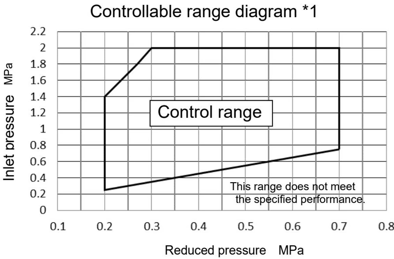
It can be used under the condition that the maximum decompression ratio is 7:1 within the controllable range shown in the figure below. If it is out of control, choose two-step decompression or another model. When the primary side pressure is 2.0 MPa, use it so that the secondary side pressure is 0.3 MPa or more.
If the pressure difference before and after the product is 0.15 MPa or more, choose the nominal size from the rated flow table below.
Rated flow table (The pressure difference before and after the product is 0.15 MPa or more)
| Nominal size | 15A | 20A | 25A | 32A | 40A | 50A | 65A | 80A | 100A |
|---|---|---|---|---|---|---|---|---|---|
| Rated flow (L/min) | 30 | 40 | 60 | 100 | 150 | 240 | 300 | 450 | 700 |
If the pressure difference before and after the product is less than 0.15 MPa, choose the nominal size from the nominal size selection charts below.
Nominal size selection chart Nominal size 20A - 50A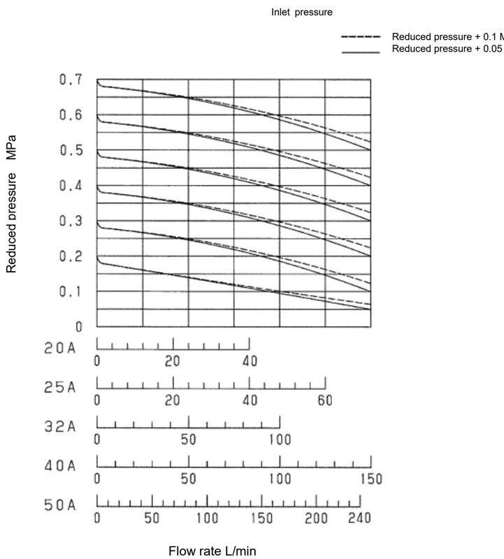
Nominal size selection chart Nominal size 65A - 100A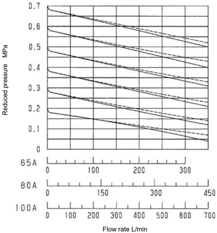
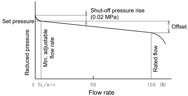
| Nominal size | Pressure range | Reduced pressure range | Offset |
|---|---|---|---|
| 20A-100A | A | 0.20-0.35 MPa | 0.10 MPa or less |
| 20A-100A | B | 0.30-0.70 MPa | 0.15 MPa or less |
| (Differential pressure after valve seat 0.15 MPa or more) |
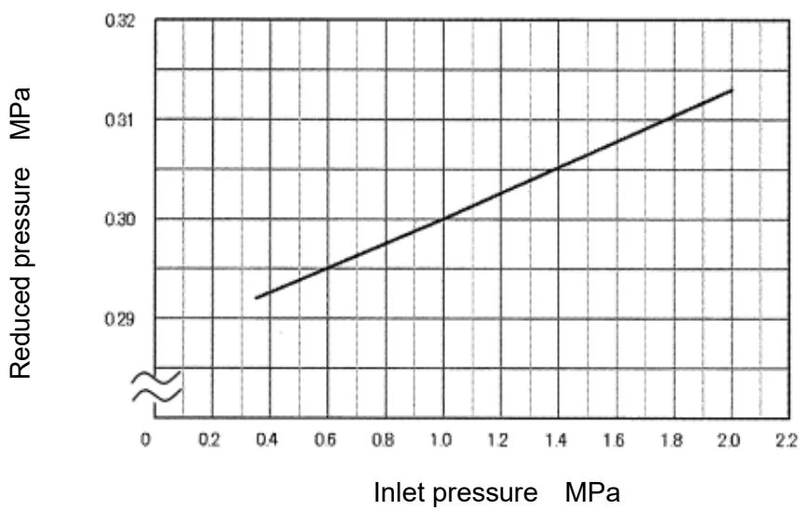 This chart shows variation in the reduced pressure when the inlet pressure of 1.0 MPa is changed between 0.35 MPa and 2.0 MPa after the reduced pressure is set at 0.30 MPa.
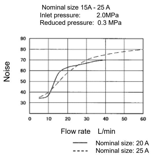 (Fluid: Water. Nominal size 32A - 50A. Inlet pressure: 2.0 MPa, Reduced pressure: 0.3 MPa)
The spring is compressed by the adjusting screw, the diaphragm is pushed down, and thereby the disc directly connected to it is opened. Fluid coming in from the inlet side flows out from the upper part of the disc to the outlet side, and passes through the reduced pressure detection hole, and is led to the bottom of the diaphragm. The load of the spring and the reduced pressure act on the diaphragm, and the upper and lower force keeps a balance and regulates the valve opening. As a result, the diaphragm keeps the reduced pressure constant.
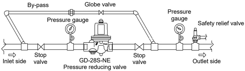
WARNING
Most problems with the pressure reducing valve are caused by foreign substances and scale in the piping. Avoid the ingress of dust and dirt to the product with caution.
| Trouble | Cause | Remedy |
|---|---|---|
| Abnormal pressure rise at the outlet side | 1. Foreign substances stuck between the disc and the valve seat, or scratch on them. 2. The O-ring is damaged. 3. The diaphragm is damaged. 4. There is a leakage from the globe valve of the by-pass line. | 1. Disassemble the product and remove the foreign substances. If scratch is observed on the valve disc or valve seat, replace it. 2. Replace the O-ring. 3. Replace the diaphragm. 4. Repair or replace the globe valve. |
| Reduced pressure does not reach the desired value | 1. The working pressure is improper. 2. The nominal size of the product is too small for the flow rate for use. 3. Pressure adjustment is improper. 4. Strainer built in the product is clogged. 5. The strainer installed at the inlet side of the product is clogged. | 1. Correct the working pressure. 2. Replace the product with the proper nominal size. 3. Readjust the pressure in accordance with the given procedure. 4. Clean the strainer. 5. Clean the strainer. |
| Outside leakage | 1. Bolt is loosened. 2. O-ring is damaged. 3. Strainer cap or plug is loosened. | 1. Tighten the bolts. 2. Replace the O-ring. 3. Tighten the strainer cap or plug. |
TIP
Replacement intervals:
Clean the strainer regularly at least once or twice a year.
Nominal size 20A - 50A: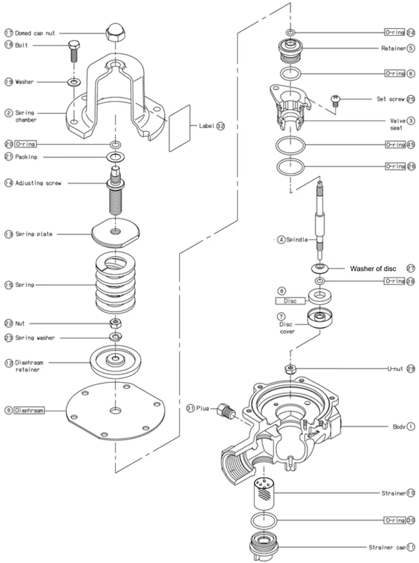
Nominal size 65A - 100A: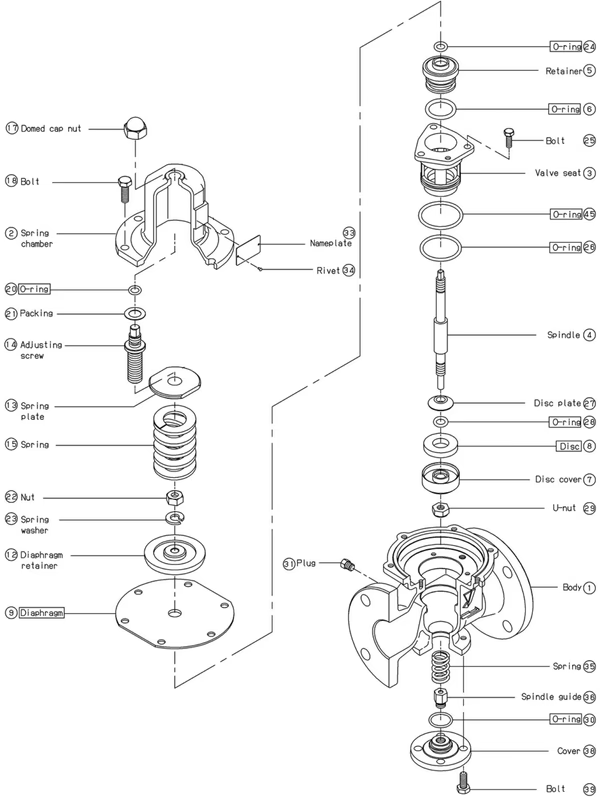
Yoshitake Control Valves / Pressure Reducing Valves
GP, GD, and CP series for stable pressure reduction and control in steam, water, and air systems.
Explore similar products in our catalog



