


PN25

Yoshitake GD-27G pressure reducing valve for air and non-dangerous fluids. Features bronze body, EPDM diaphragm, 1.0 MPa max inlet, and JIS 10K FF flanged connection.
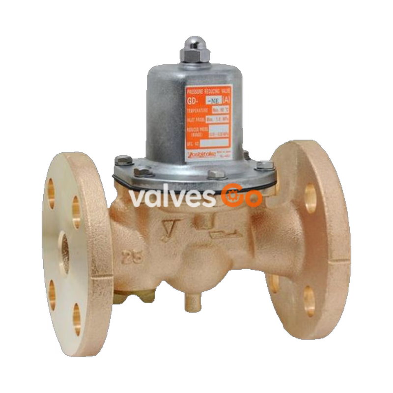
Yoshitake GD-27G is a direct type pressure reducing valve designed for air and other non-dangerous fluids. It features a bronze body and EPDM diaphragm, offering a maximum pressure reduction ratio of 10:1. The pressure balance structure maintains reduced pressure at a constant level without being affected by inlet pressure fluctuations. The wetted parts use corrosion-resistant materials, and the valve provides reduced noise operation.
The GD-27G utilizes a JIS 10K FF flanged connection (available in nominal sizes 25A to 100A), while the related GD-26G uses a JIS Rc screwed connection. Maintenance and inspection can be performed easily by disassembling the unit from the upper side.
| Model | GD-27G | GD-26G |
|---|---|---|
| Application | Air, Other non-dangerous fluids * | Air, Other non-dangerous fluids * |
| Inlet pressure | 1.0 MPa or less | 1.0 MPa or less |
| Reduced pressure | (A) 0.05-0.35 MPa (B) 0.3-0.7 MPa | (A) 0.05-0.35 MPa (B) 0.3-0.7 MPa |
| Fluid temperature | 5-90℃ | 5-90℃ |
| Minimum differential pressure | 0.05 MPa | 0.05 MPa |
| Maximum pressure reduction ratio | 10:1 | 10:1 |
| Body material | Bronze | Bronze |
| Valve seat material | Bronze | Bronze |
| Valve disc material | EPDM | EPDM |
| Diaphragm material | EPDM | EPDM |
| Connection | JIS 10K FF flanged | JIS Rc screwed |
Notes
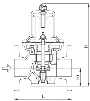
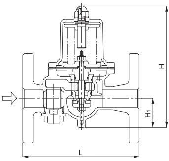
| Nominal size | L (mm) | H (mm) | H1 (mm) | Weight (kg) |
|---|---|---|---|---|
| 25A | 160 | 170 | 41 | 5.1 |
| 32A | 200 | 224 | 57 | 7.5 |
| 40A | 200 | 224 | 57 | 7.7 |
| 50A | 220 | 239.5 | 61 | 10.9 |
| 65A | 220 | 329 | 77 | 20.0 |
| 80A | 230 | 345 | 82 | 22.0 |
| 100A | 270 | 412 | 94 | 33.0 |
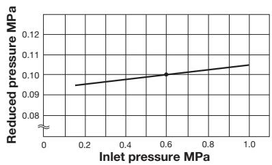 This chart shows variation in reduced pressure when the inlet pressure of 0.6 MPa is changed between 0.15 MPa and 1.0 MPa while the reduced pressure is set at 0.1 MPa.
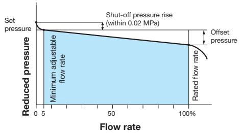
| Nominal size | Pressure range | Offset pressure |
|---|---|---|
| 15-100A | (A) 0.05-0.35 MPa | Within 0.05 MPa |
| 15-100A | (B) 0.3-0.7 MPa | Within 0.10 MPa |
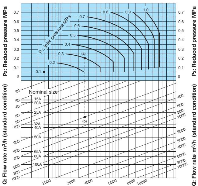
Selection Example
When selecting the nominal size of a pressure reducing valve whose inlet pressure (P1), reduced pressure (P2), and flow rate are 0.3 MPa, 0.2 MPa, and 200 m³/h (standard condition), respectively:
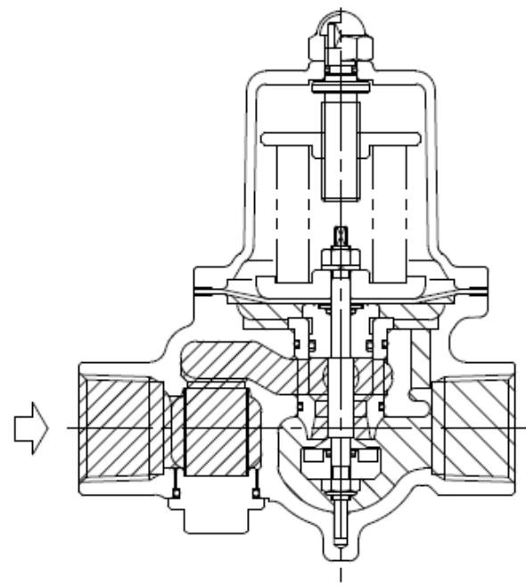
The adjusting screw compresses the adjusting spring, pushes down on the diaphragm, and opens the disc that is directly connected to it. The fluid that entered from the primary side flows out from the upper part of the disk to the secondary side, and at the same time, acts directly on the diaphragm as the secondary side pressure.
When the sluice valve on the secondary side is closed, the pressure applied to the diaphragm increases, overcomes the load of the adjustment spring, and the disc closes. Gradually opening the sluice valve on the secondary side reduces the pressure applied to the diaphragm and opens the disc. The fluid flowing out to the secondary side acts on the diaphragm as the secondary side pressure, balances with the load of the adjustment spring, adjusts the valve opening, and keeps the secondary side pressure constant.
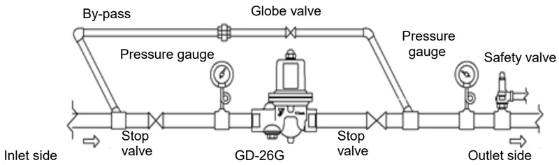
Installation Precautions
Yoshitake Control Valves / Pressure Reducing Valves
GP, GD, and CP series for stable pressure reduction and control in steam, water, and air systems.
Explore similar products in our catalog



