PN16

Yoshitake DP-200-N and DP-200F-N pilot-operated solenoid valves offer zero leakage, JWWA approval, and 0-1.0 MPa working pressure for water, air, and gas.
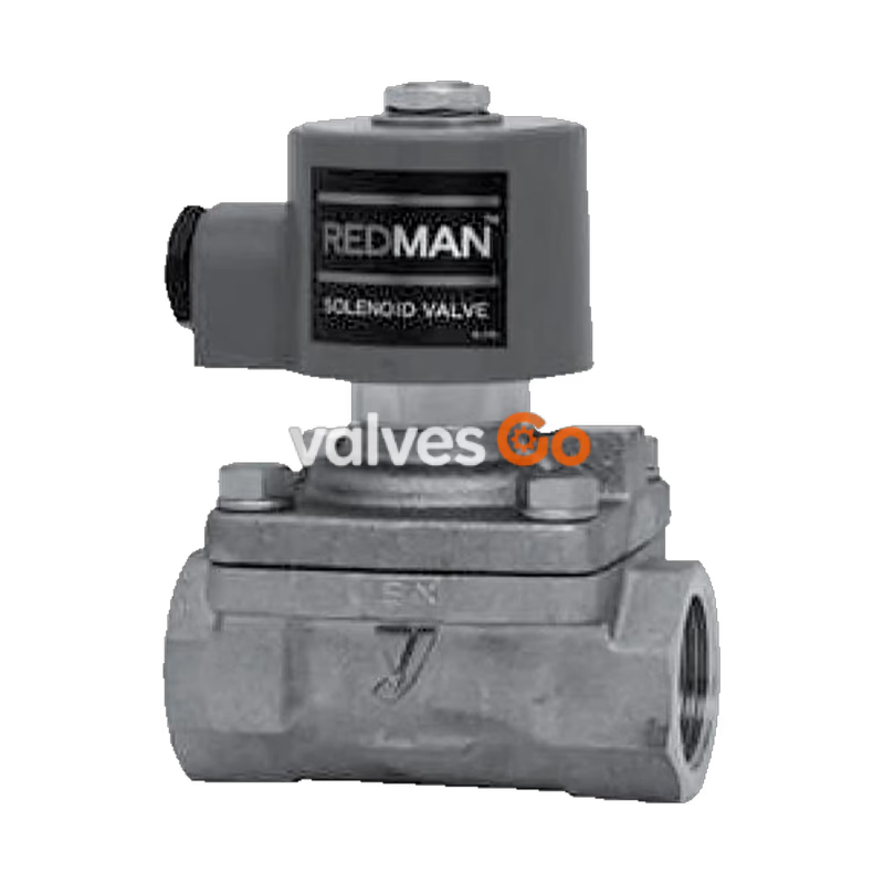
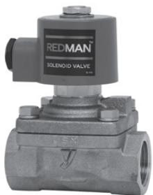
The Yoshitake DP-200-N series pilot-operated solenoid valves are designed for automatic on-off control of fluid flow. Approved by the Japanese Water Works Association (JWWA), these valves feature a synthetic rubber valve part that ensures zero leakage. They effectively reduce water hammer shocks and shorten closing times. The DP-200-N can be used as a pilot solenoid valve for constant water level valves of 65A and larger.

| Model | DP-200-N | DP-200F-N |
|---|---|---|
| Normally Closed | Yes | Yes |
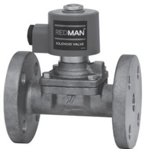
| Nominal Size | 10A–50A (15A-50A for F) | 15A–50A |
| Structure | Pilot-operated diaphragm type | Pilot-operated diaphragm type |
| Application | Cold and Hot water, Air, N2 gas, CO2 gas (dry), Ar gas, Oil (20 cSt or less) | Cold and Hot water, Air, N2 gas, CO2 gas (dry), Ar gas, Oil (20 cSt or less) |
| Working Pressure | 0–1.0 MPa (Unusable under vacuum) | 0–1.0 MPa (Unusable under vacuum) |
| Min. Differential Pressure | 0 MPa (0.1 MPa or more is required if the coil is set sideways) | 0 MPa (0.1 MPa or more is required if the coil is set sideways) |
| Allowable Valve Seat Leakage | None (by confirming pressure gauge visually) | None |
| Temperature Range | 5–60°C (no freeze condition) | 5–60°C (no freeze condition) |
| Ambient Temperature | 50°C or less (no freeze condition) | 50°C or less (no freeze condition) |
| Installation Posture | Vertical or horizontal (within 90 degrees from upward position) | Vertical or horizontal |
| Material (Body/Valve) | Bronze (NPb-treated) | Bronze (NPb-treated) |
| Material (Diaphragm) | NBR | NBR |
| Connection | JIS Rc screwed | JIS 10K FF flanged |
INFO
Available with rubber material FKM for the diaphragm. Max. temperature: 90°C (only for standard DP-200 and DP-200F). When using the solenoid valve to pilot piping of a constant water level valve (up to 50A), direct type DD-3-8N is recommended.
| Item | AC 100 / 200 V selective type | AC 110 / 220 V selective type |
|---|---|---|
| Frequency | 50 / 60 Hz common | 50 / 60 Hz common |
| Allowable Fluctuation | Rated voltage –5% to +10% | Rated voltage –5% to +10% |
| Rated Current | 0.42 / 0.21 A | 0.38 / 0.19 A |
| Starting Current | 1.64 / 0.82 A | 1.48 / 0.74 A |
| Insulation Class | Class H | Class H |
| Protective Structure | Dust tight, Splash proof | Dust tight, Splash proof |
| Ingress Protection Code | IP64 (JIS C0920) | IP64 (JIS C0920) |
| Insulation Resistance | 50 MΩ and more / 500 V megger | 50 MΩ and more / 500 V megger |
| Withstand Voltage Test | 1500 V/min | 1500 V/min |
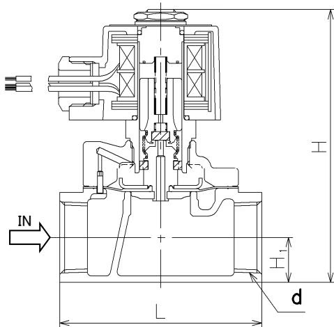
| Nominal Size | d | L | H1 | H | Weight (kg) |
|---|---|---|---|---|---|
| 10A | Rc 3/8 | 70 | 14.5 | 114 | 1.1 |
| 15A | Rc 1/2 | 70 | 14.5 | 114 | 1.1 |
| 20A | Rc 3/4 | 80 | 17.5 | 121 | 1.3 |
| 25A | Rc 1 | 95 | 21.0 | 128 | 1.7 |
| 32A | Rc 1-1/4 | 110 | 26.0 | 150 | 2.5 |
| 40A | Rc 1-1/2 | 120 | 29.5 | 157 | 3.1 |
| 50A | Rc 2 | 140 | 36.5 | 172 | 5.0 |
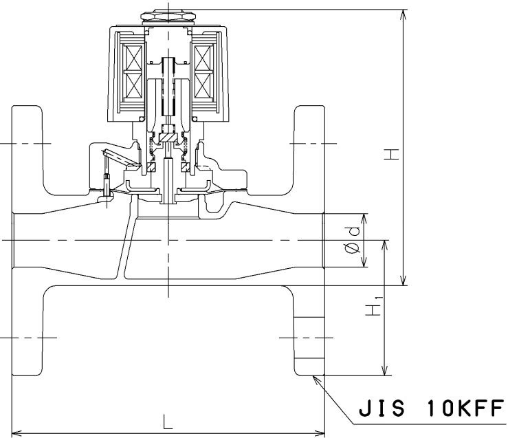
| Nominal Size | d | L | H1 | H | Weight (kg) |
|---|---|---|---|---|---|
| 15A | 15 | 120 | 47.5 | 147 | 2.7 |
| 20A | 20 | 130 | 50.0 | 153 | 3.3 |
| 25A | 25 | 145 | 62.5 | 169 | 4.8 |
| 32A | 32 | 160 | 67.5 | 192 | 6.6 |
| 40A | 40 | 170 | 70.0 | 198 | 7.3 |
| 50A | 50 | 195 | 77.5 | 213 | 10.0 |
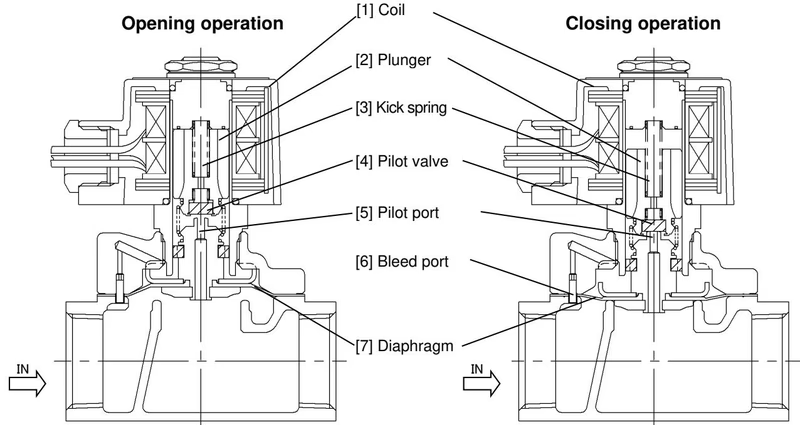
When the power is turned ON, the coil is excited and pulls up the plunger, opening the pilot valve. Next, the pressure at the upper part of the diaphragm drops since it flows to the outlet through the pilot port. The diaphragm is then lifted up to the open position by the inlet pressure.
When the power is turned OFF, the coil excitation is canceled and the plunger drops down by the force of the kick spring, closing the pilot valve. The pressure at the upper part of the diaphragm rises due to the incoming inlet pressure from the bleed port which communicates with the inlet. With the support of the kick spring, the diaphragm is pushed down to the closed position.
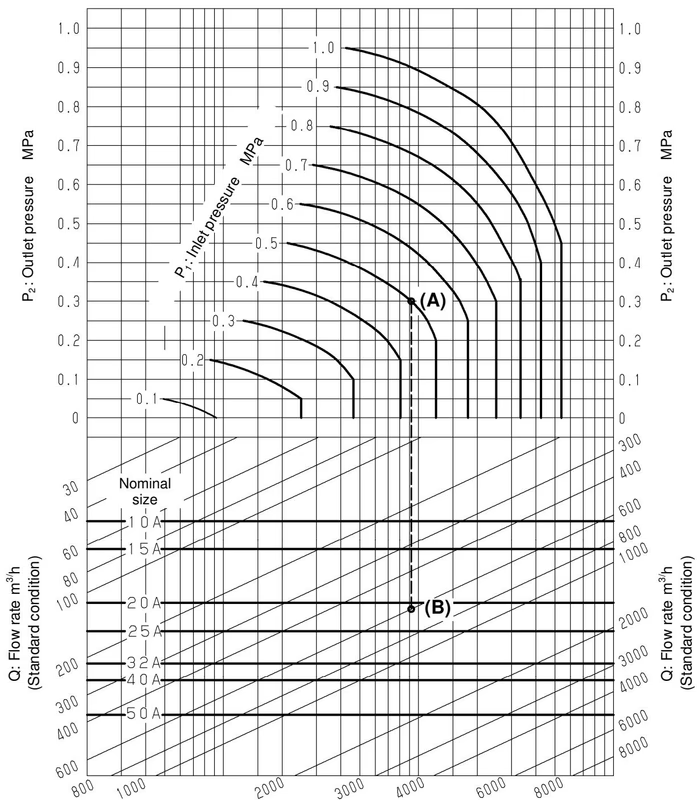
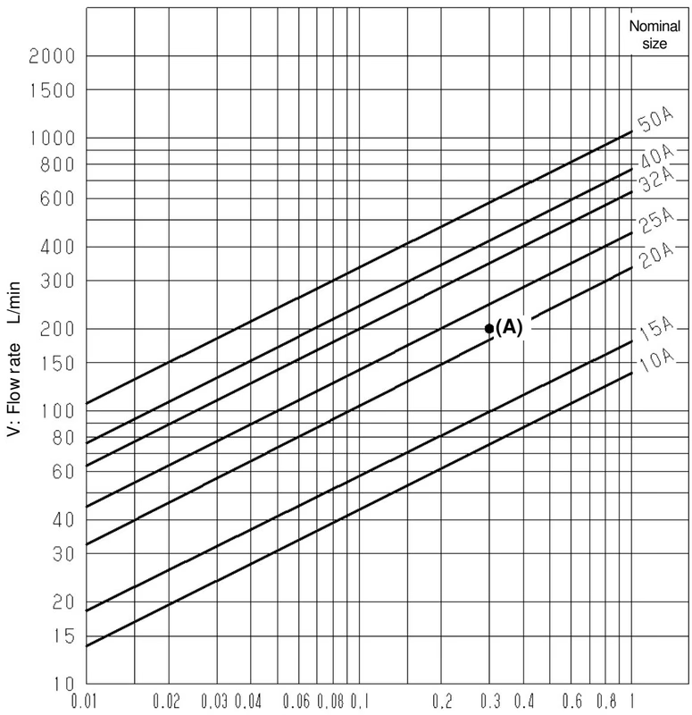
| Nominal Size | 10A | 15A | 20A | 25A | 32A | 40A | 50A |
|---|---|---|---|---|---|---|---|
| Cv Value | 3 (1.2) | 4 (1.7) | 7.5 (3.2) | 10 (4.6) | 14 (5.5) | 17 (6.5) | 24 (9.5) |
Cv values in parentheses are values when the differential pressure is 0.01 MPa or less.
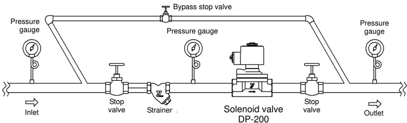
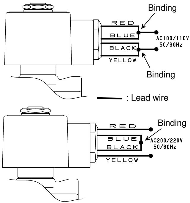
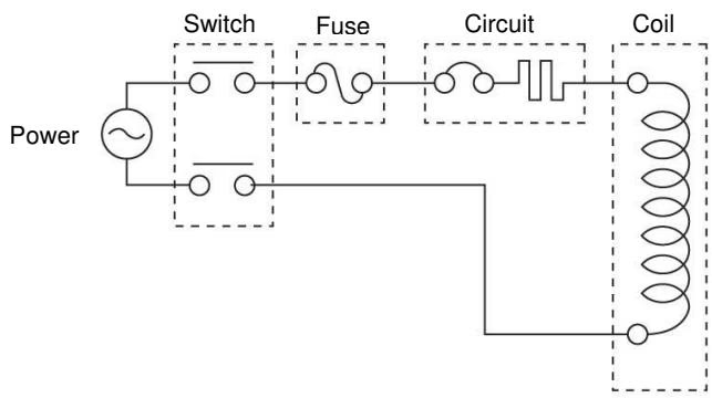
Installation Precautions
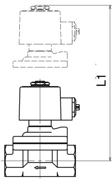
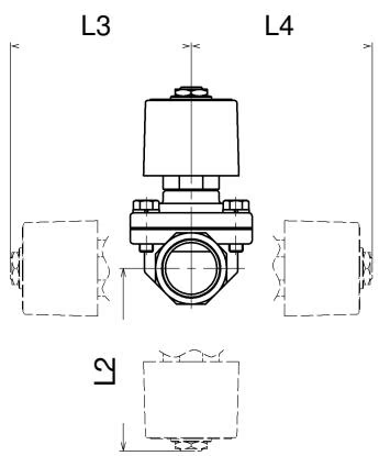
Conduct daily and periodic inspections in order to maintain optimal performance. Disassembly and maintenance must be done by experienced professionals.
Periodic replacement of parts:

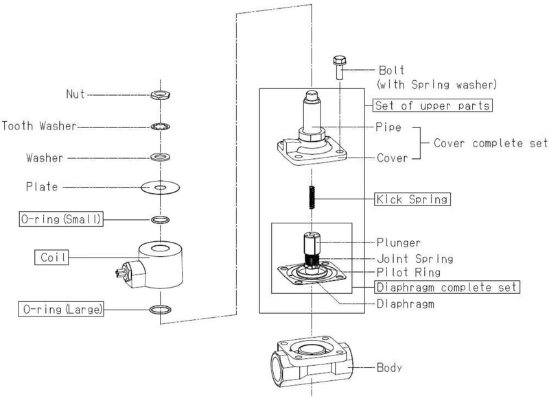
Insert the diaphragm complete set with the kick spring into the cover complete set. 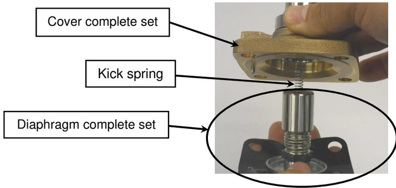
Push the diaphragm and check that it moves smoothly. If the kick spring drops off, it will not operate normally. 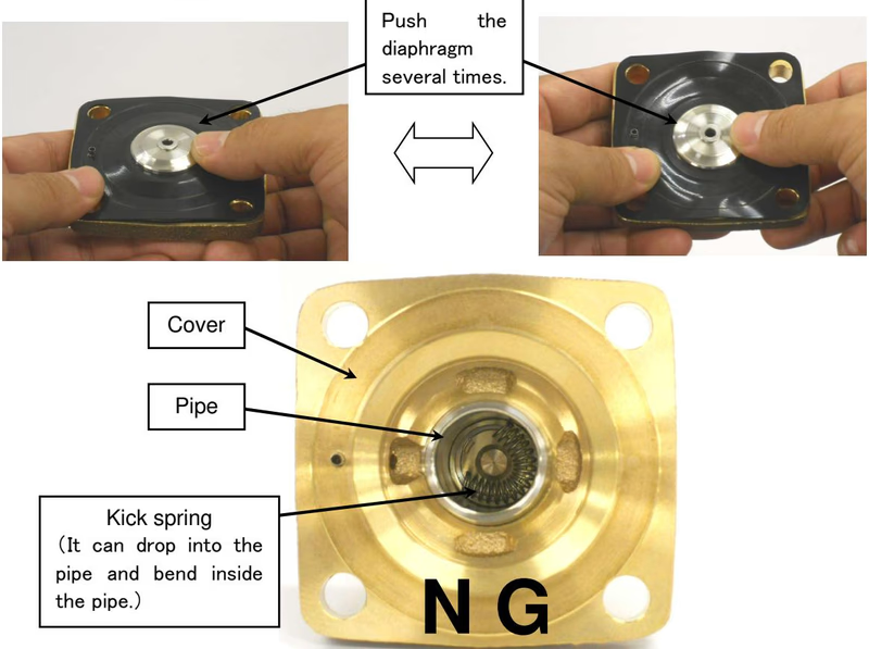
When installing the cover complete set to the body, insert the spring pin into the bleed port (pin hole). 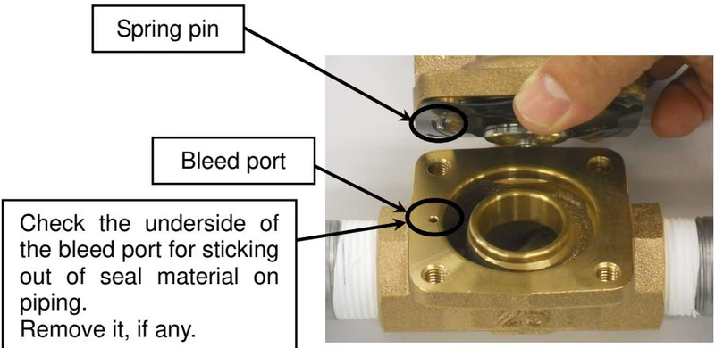
Yoshitake Actuation & Positioners / Solenoid
DD and DP series solenoid valves for automatic fluid shutoff and interlocking control.
Explore similar products in our catalog