Lift Type

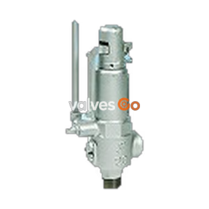
Yoshitake AL-32TML safety relief valve. Features lever type closed structure, stainless steel construction, and soft seat for non-leakage applications. Working pressure 0.05-1.0 MPa.
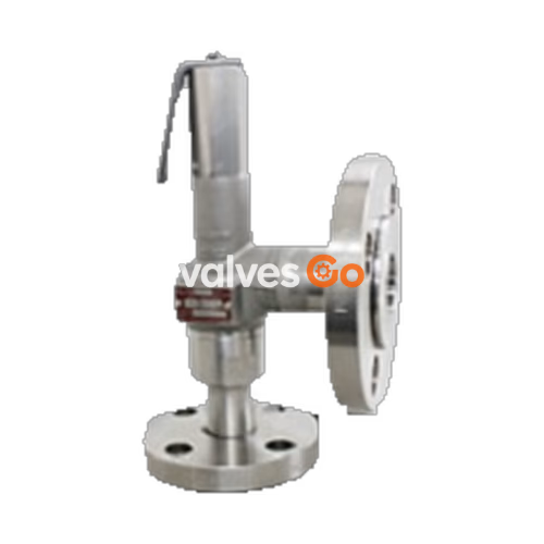
Yoshitake AL-32TML is a closed-type safety relief valve with a lever, designed for applications requiring high air tightness where valve seat leakage is not tolerated. Constructed from cast stainless steel with a soft seat (O-ring) design, it prevents fluid leakage and offers excellent corrosion resistance. The valve is suitable for air, water, oil, and other non-dangerous fluids, operating at pressures between 0.05 and 1.0 MPa.
Required Differential Pressure at a Discharge Inspection
| Nominal size | Difference between set pressure at a discharge inspection |
|---|---|
| 15A-25A | 1.0 MPa or less |
| 32A, 40A | 0.6 MPa or less |
| 50A | 0.4 MPa or less |
| Structure | Closed type with a lever |
|---|---|
| Application | Air, water, oil, other non-dangerous fluids |
| Working pressure | 0.05-1.0 MPa |
| Working temperature | 5-120°C |
| Material (Spring case) | Cast stainless steel |
| Material (Valve, valve seat) | Stainless steel (Valve: SCS14A, Seat: SUS316) |
| Material (Adjusting spring) | Stainless steel |
| Material (O-ring) | Synthetic rubber (FKM) |
| Connection | JIS 10K loose flange |
INFO
Please contact the manufacturer when using for oil. The maximum temperature is 150°C when the fluid is liquid.
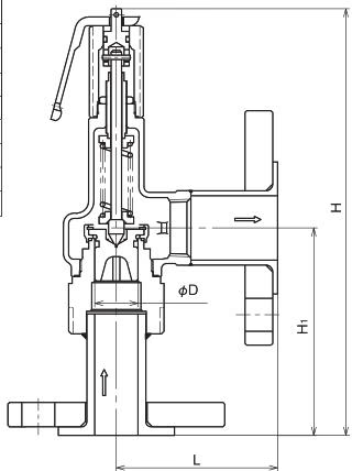
| Nominal size | Dimensions D (mm) | Dimensions L (mm) | Dimensions H₁ (mm) | Dimensions H (mm) | Flow area πD² (mm²) | Weight (kg) |
|---|---|---|---|---|---|---|
| 15A | 16 | 63 | 97 | 215 | 20.1 | 2.5 |
| 20A | 21 | 87 | 101 | 217 | 34.6 | 2.9 |
| 25A | 26 | 92 | 119 | 245 | 53.0 | 4.5 |
| 32A | 33 | 99 | 135 | 284 | 93.3 | 5.3 |
| 40A | 41 | 109 | 140 | 321 | 135.2 | 6.7 |
| 50A | 51 | 114 | 162 | 372 | 208.2 | 11.5 |
INFO
The outlet flange is 1 size larger than the nominal size.
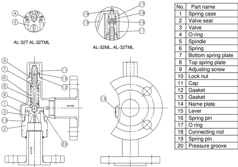
Blowout Operation: As the inlet pressure approaches the blowout pressure, the force of the fluid pushing up the valve approaches the force of the spring pressing it down. The valve commences to blow when the inlet pressure reaches around 3% below the blowout pressure. The fluid accumulates on the pressure groove and pops the valve when the fluid pressure reaches the blowout pressure.
Closing Operation: When the fluid is released, the inlet pressure decreases, lowering the fluid lift force. The repelling force of the spring becomes larger than the fluid lift force, closing the valve. Back pressure from fluid entering the back of the valve also adds to the closing force.
Capacity (kg/h) <Pressure vessel structure standard>
| Nominal size | 0.1 MPa | 0.2 MPa | 0.3 MPa | 0.4 MPa | 0.5 MPa | 0.6 MPa | 0.7 MPa | 0.8 MPa | 0.9 MPa | 1.0 MPa |
|---|---|---|---|---|---|---|---|---|---|---|
| 15A | 33 | 48 | 65 | 81 | 98 | 114 | 131 | 147 | 164 | 181 |
| 20A | 57 | 83 | 111 | 140 | 169 | 197 | 226 | 254 | 283 | 311 |
| 25A | 87 | 127 | 171 | 215 | 258 | 302 | 346 | 390 | 433 | 477 |
| 32A | 147 | 214 | 288 | 362 | 435 | 509 | 582 | 656 | 730 | 803 |
Capacity (m³/h) <Yoshitake standard>
| Nominal size | 0.1 MPa | 0.2 MPa | 0.3 MPa | 0.4 MPa | 0.5 MPa | 0.6 MPa | 0.7 MPa | 0.8 MPa | 0.9 MPa | 1.0 MPa |
|---|---|---|---|---|---|---|---|---|---|---|
| 15A | 0.5 | 0.9 | 1.1 | 1.3 | 1.5 | 1.6 | 1.8 | 1.9 | 2.0 | 2.1 |
| 20A | 0.9 | 1.6 | 2.0 | 2.3 | 2.6 | 2.8 | 3.1 | 3.3 | 3.5 | 3.7 |
| 25A | 1.5 | 2.5 | 3.1 | 3.6 | 4.0 | 4.4 | 4.7 | 5.1 | 5.4 | 5.7 |
| 32A | 2.6 | 4.5 | 5.5 | 6.3 | 7.1 | 7.8 | 8.4 | 9.0 | 9.5 | 10.0 |
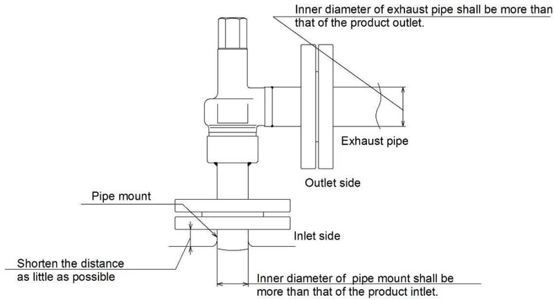
WARNING
Yoshitake Safety Valves / Relief Valves
AF and AL series safety and relief valves for overpressure protection of steam, water, and air equipment.
Explore similar products in our catalog