Repairable

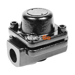
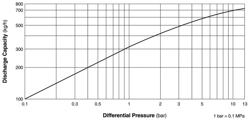
TLV LV13L brass balanced pressure thermostatic steam trap with fail-open design for tracing and small processes. Up to 1.3 MPaG (13 barg) and 200°C.
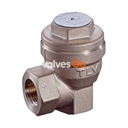
TLV LV13L is a balanced pressure thermostatic steam trap constructed with a brass body, featuring a reliable "fail open" design that prevents condensate from holding back in the steam space. This compact yet high-capacity trap is highly suitable for small processes, tracing lines, vessels, and heaters, accommodating operating pressures up to 13 barg (1.3 MPaG) and temperatures up to 200°C.
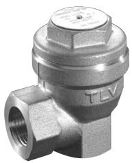
| Model | LV13L |
|---|---|
| Connection | Screwed (BSP DIN 2999, other standards available) |
| Size | 1/2", 3/4" |
| Maximum Operating Pressure (PMO) | 13 barg (1.3 MPaG) |
| Minimum Operating Pressure | 0.1 barg |
| Maximum Back Pressure | 90% of Inlet Pressure |
| Maximum Operating Temperature (TMO) | 200 °C |
| Subcooling of X-element Fill | Up to 6 °C |
| Type of X-element | C6 |
WARNING
PRESSURE SHELL DESIGN CONDITIONS (NOT OPERATING CONDITIONS): Maximum Allowable Pressure (PMA): 16 barg (1.6 MPa) Maximum Allowable Temperature (TMA): 220 °C To avoid abnormal operation, accidents, or serious injury, DO NOT use this product outside of the specification range.
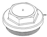
| No. | Description | Material | DIN Equivalent | ASTM/AISI Equivalent |
|---|---|---|---|---|
| 1 | Body | Brass C3771 | 2.0380 | B124 C37700 |
| 2 | Cover | Brass C3771 | 2.0380 | B124 C37700 |
| 3 | Valve Seat* | Stainless Steel SUS420F | 1.4028 | AISI 420F |
| 4 | X-element* | Stainless Steel | - | - |
| 5 | X-element Guide* | Stainless Steel SUS304 | 1.4301 | AISI 304 |
| 6 | Spring Clip* | Stainless Steel SUS304 | 1.4301 | AISI 304 |
| 7 | Screen* | Stainless Steel SUS304 | 1.4301 | AISI 304 |
| 8 | Cover Gasket* | Fluorine Resin PTFE | PTFE | PTFE |
| 9 | Nameplate | Stainless Steel SUS304 | 1.4301 | AISI 304 |
| (Parts marked with * are available in replacement repair kits). |
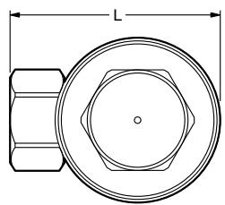
| Size | L (mm) | H (mm) | φW (mm) | A (mm) | B (mm) | Weight (kg) |
|---|---|---|---|---|---|---|
| 1/2" | 64 | 70 | 52 | 20 | 38 | 0.5 |
| 3/4" | 66 | 77 | 52 | 27 | 40 | 0.5 |
TIP
The LV13L can be maintained without being removed from the pipeline, provided the surrounding pipes are securely supported. It is installed in pipelines with a horizontal inlet and vertical outlet (cover facing up).
Explore similar products in our catalog