


PN16

The TLV JH7RH-P is a low alloy cast steel free float steam trap with a cover threaded plug, designed for high-pressure and high-temperature process equipment up to 530°C and 120 barg.
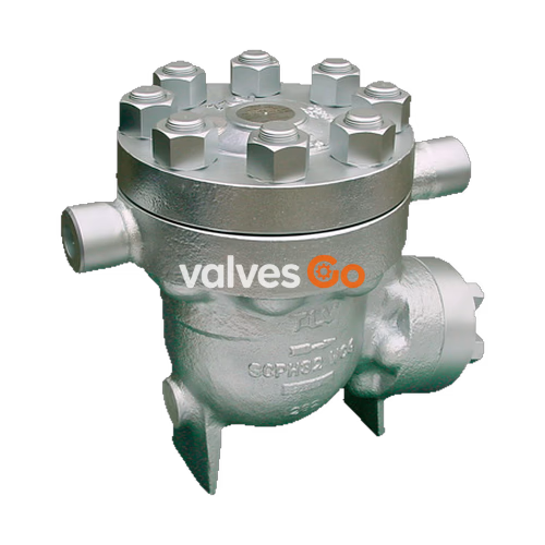
The TLV JH7RH-P is a reliable and durable low alloy cast steel free float steam trap for use on medium-size process equipment, suitable for both superheated and extremely high-pressure applications. Instead of a bimetal air vent, it is manufactured with a cover threaded plug for higher pressure and temperature applications. The inline repairable design features a self-modulating free float that provides continuous, smooth, low-velocity condensate discharge as process loads vary, along with a precision-ground float, constant water seal, and three-point seating design that ensures a steam-tight seal even under no-load conditions.
DANGER
NEVER apply direct heat to the float. The float may explode due to increased internal pressure, causing accidents leading to serious injury or damage to property and equipment.
WARNING
To avoid malfunctions, product damage, accidents or serious injury, install properly and DO NOT use this product outside the specifications' range. DO NOT use traps under conditions that exceed maximum differential pressure, as condensate backup will occur!
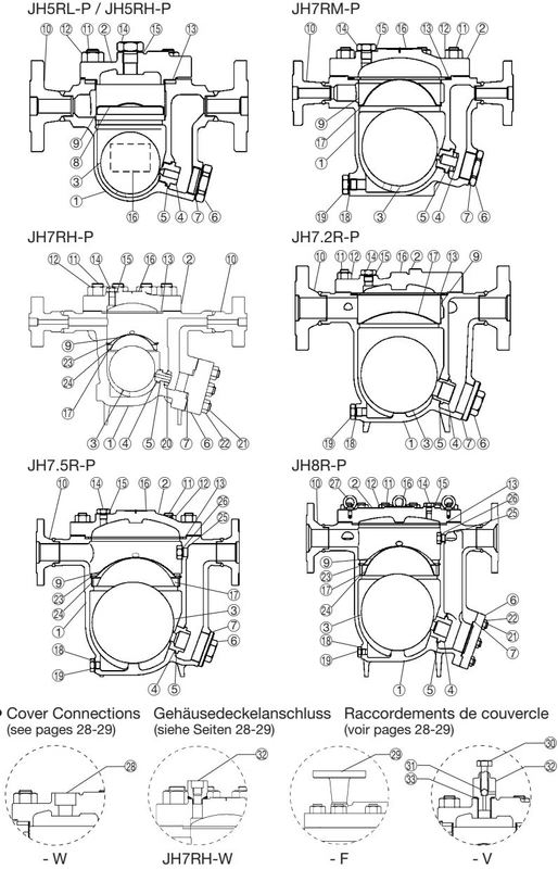
| No. | Description | No. | Description |
|---|---|---|---|
| 1 | Body | 12 | Cover Nut |
| 2 | Cover | 13 | Cover Gasket |
| 3 | Float | 14 | Cover Plug |
| 4 | Orifice | 15 | Cover Plug Gasket |
| 5 | Orifice Gasket | 16 | Nameplate |
| 6 | Orifice Plug or Outlet Cover | 17 | Screen Holder |
| 7 | Plug or Outlet Cover Gasket | 18 | Drain Plug Gasket* |
| 8 | Float Cover | 19 | Drain Plug* |
| 9 | Screen | 20 | Locknut |

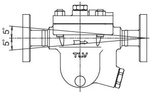
Check to make sure that the pipes connected to the trap have been installed properly.
Operational inspections should be performed at least twice per year, or as called for by trap operating conditions.
| Parts Inspection Procedure | |
|---|---|
| Body, Cover(s) | Check inside for damage, dirt, grease, oil film, rust or scale |
| Gaskets | Check for warping or damage |
| Screen | Check for clogging, corrosion or damage |
| Float | Check for deformation, damage, oil film or water inside |
| Valve Seat | Check for rust, scale, oil film, wear or damage |
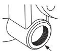
The seal on the threaded plugs/holders found on TLV products is formed by a flat metal gasket.
A visual inspection can be carried out to aid in determining the necessity for immediate maintenance or repair.
| Condition | Description |
|---|---|
| Normal | Condensate is discharged continuously with flash steam and the sound of flow can be heard. |
| Blocked | No condensate is discharged. The trap is quiet and makes no noise, and the surface temperature of the trap is low. |
| Blowing | Live steam continually flows from the outlet and there is a continuous metallic sound. |
| Steam Leakage | Live steam is discharged through the trap outlet together with the condensate and there is a high-pitched sound. |
Flash steam (White jet with water droplets): 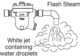
Live steam leakage (Clear, slightly bluish jet): 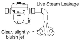
| Problem | Cause | Remedy |
|---|---|---|
| No condensate is discharged (blocked) or discharge is poor | Float is damaged or filled with condensate | Replace the float |
| Orifice, screen or piping are clogged with rust or scale | Clean | |
| Steam-locking has occurred | Blowdown through the bypass or close the trap inlet valve and allow the trap to cool | |
| Flow exceeds rated capacity of the trap | Check specifications and reselect trap suitable for actual flow | |
| Air binding has occurred | Perform a bypass blowdown or consider switching to a product with a built-in air vent or air vent valve | |
| The trap operating pressure exceeds the maximum specified pressure, or there is insufficient pressure differential | Compare specifications and actual operating conditions |




