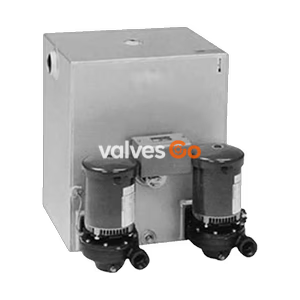
3450 RPM Motors

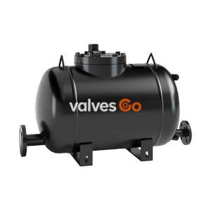
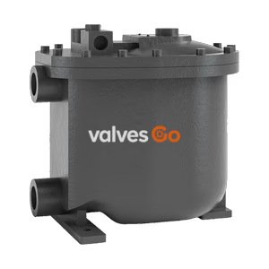
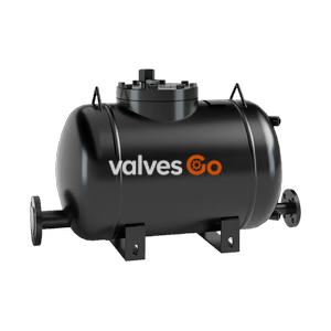
The TLV PowerTrap GP14-B is a mechanical pump designed to discharge condensate from vacuum or low-pressure areas to high-pressure areas. Suitable for open and closed systems.
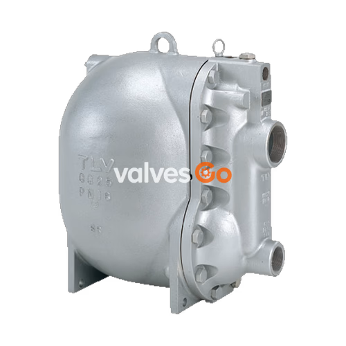
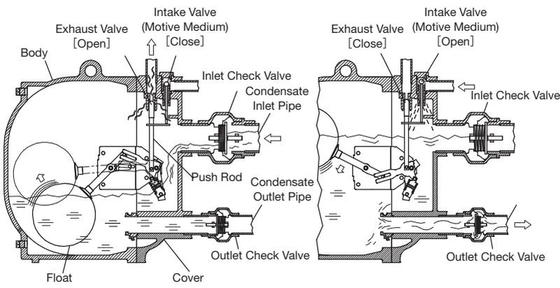
The TLV PowerTrap GP14-B is a mechanical pump used to discharge liquid from vacuum-pressure or low-pressure areas to high-pressure areas, or from lower to higher elevations. It features an integrated pumping function that can eliminate and pump out condensate even if it cannot be discharged due to very low supply steam pressure because of reduced load in the steam-using equipment (a phenomenon known as 'stall'). This model is suitable for both closed and open delivery systems.
WARNING
Take measures to prevent people from coming into direct contact with product outlets. Failure to do so may result in burns or other injury from the discharge of fluids.
DANGER
Install properly and DO NOT use this product outside the recommended operating pressure, temperature and other specification ranges. Use only under conditions in which no freeze-up will occur. Freezing may damage the product, leading to fluid discharge, which may cause burns or other injury.
| Specification | Value |
|---|---|
| Motive Medium Pressure Range | 0.03 - 1.4 MPaG (5 - 200 psig) |
| GP14-B (Cast Iron in Europe) | 0.03 - 1.3 MPaG (5 - 185 psig) |
| Maximum Allowable Back Pressure | 0.05 MPa (7 psi) less than motive medium pressure used (but not to exceed 1.05 MPaG / 150 psig) |
Note: Maximum allowable pressure (PMA) and maximum allowable temperature (TMA) are PRESSURE SHELL DESIGN CONDITIONS, NOT OPERATING CONDITIONS.
The GP14-B supports both Closed and Open systems.
| Type of System | Closed System | Open System |
|---|---|---|
| Benefits | Use with vacuum equipment possible. | Collection of condensate from multiple equipment possible. Can be used where trap is lower than receiver. |
| Notes | Only one piece of equipment possible per system. Equipment has minimum height requirement (approx. 1 m). | Separate steam trap required for each piece of equipment. Requires venting pipe to discharge flash steam. |
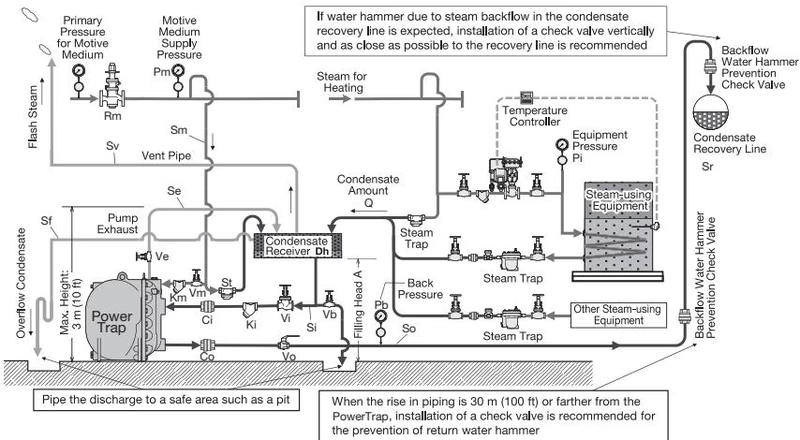
NOTE: This sketch is for explanation purposes only and is not intended as an installation design.
It is necessary to install a condensate receiver for storing condensate during pumping, as condensate cannot enter the PowerTrap while it is discharging.
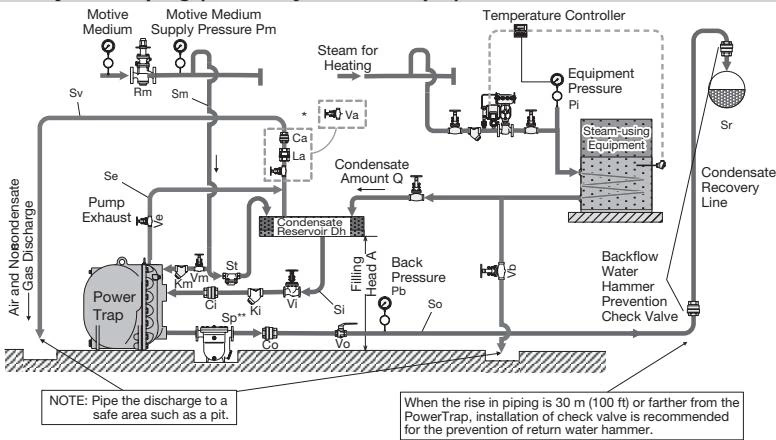
If the pressure at the PowerTrap inlet exceeds the pressure at the PowerTrap outlet, make sure to install a steam trap at the PowerTrap outlet. Steam will blow if no steam trap is installed.
WARNING
Use hoisting equipment for heavy objects (weighing approximately 20 kg or more). Failure to do so may result in back strain or other injury if the object should fall.
Fluids that can be discharged through the PowerTrap are limited to steam condensate, water and non-flammable, non-toxic fluids with specific gravities 0.85 – 1.0.
Explore similar products in our catalog