

PN16

BURKERT 48171 is a Type 0290 servo-assisted 2/2-way solenoid valve with brass body, G 1 thread, DN 25 orifice, NBR seal, and 24 V 50 Hz coil, operating from 0 to 16 bar without differential pressure.
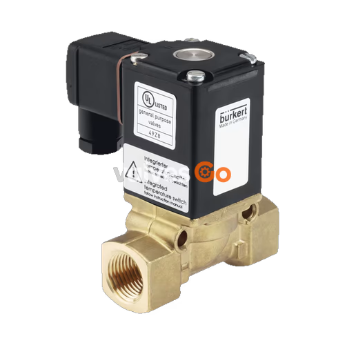
BURKERT 48171 is a Type 0290 servo-assisted 2/2-way diaphragm solenoid valve configured with a brass body, G 1 internal thread connections, and an internal orifice of DN 25 (25 mm). The valve opens reliably without requiring an operating differential pressure, covering a pressure span from 0 to 16 bar. Opening movement is supported by the fix-coupling between the main diaphragm and the magnetic core, while an integrated soft-kick function ensures gentle opening cycles. The magnetic coil is moulded in epoxy resin with thermal insulation class H, operating on 24 V AC at 50 Hz. Media sealing is provided by NBR elastomers for both the seat and external boundary, supporting media temperatures between -10 °C and +80 °C.
The valve operates according to Circuit Function A (CF A). It is a 2/2-way servo-assisted solenoid valve that remains closed in the de-energized, unpowered state. When electrical power is applied to the coil, the magnetic plunger lifts the pilot seal and mechanically pulls the fix-coupled diaphragm off the valve orifice, enabling media flow from inlet port 1 (P) to outlet port 2 (A).
| Parameter | Specification |
|---|---|
| Type | 0290 |
| Article number | 48171 (048171) |
| Circuit function | A (2/2-way, normally closed) |
| Nominal orifice (DN) | 25 mm (1") |
| Pilot control orifice | 2 mm |
| Port connection | G 1 internal thread |
| Operating pressure | 0 to 16 bar |
| Kv value (water, P → A) | 10.0 m³/h |
| QNn value (gas) | 10,700 l/min |
| Rated voltage | 24 V AC, 50 Hz |
| Voltage tolerance | ±10% |
| Electrical power consumption | Inrush: 120 VA; Holding: 32 VA (16 W) |
| Thermal insulation class | Class H (epoxy coil) |
| Duty cycle | 100% ED continuous operation |
| Switching times (opening / closing) | 100 to 250 ms / 700 to 2000 ms (measured at +20 °C, 6 bar outlet) |
| Body material | Brass |
| Seal material | NBR |
| Medium compatibility | Neutral gases and liquids (compressed air, water, hydraulic oils, oils without additives) |
| Medium temperature range | -10 °C to +80 °C |
| Maximum ambient temperature | +55 °C |
| Degree of protection | IP65 (with cable plug attached) |
| Electrical connection | DIN EN 175301-803 Form A plug (cable plug enclosed) |
| Weight | 1.8 kg |
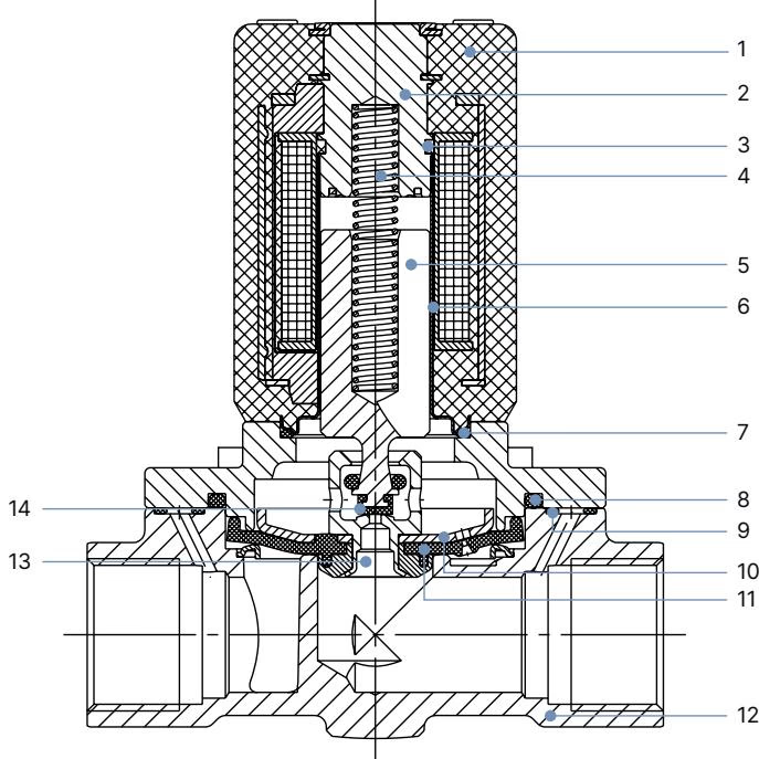
| Item | Component | Material in Article 48171 (Type 0290 Family) |
|---|---|---|
| 1 | Coil | Epoxy |
| 2 | Stopper | Stainless steel 1.4105, 1.4113 or 1.4523 |
| 3 | Shading ring (AC only) | Copper (Brass variant) / Silver (Stainless steel variant) |
| 4 | Spring | Stainless steel 1.4310 |
| 5 | Magnetic core (armature) | Stainless steel 1.4105 or 1.4113 |
| 6 | Core guide tube | Stainless steel 1.4303 |
| 7, 8, 9 | O-rings | NBR (NBR, FKM, EPDM across variants) |
| 10 | Diaphragm plate | CuZn37 (Brass variant) / 1.4401 (Stainless steel variant) |
| 11 | Diaphragm | NBR |
| 12 | Body | Brass (MS) |
| 13 | Pilot valve seat | Brass (MS) |
| 14 | Seat seal | NBR |
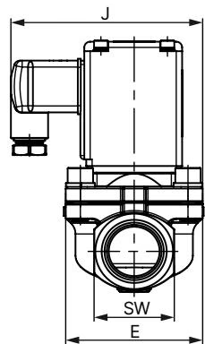
Dimensions for threaded body variants of Type 0290 are stated in millimeters (mm). For G threads, columns D1 and F1 apply; for NPT threads, D2 and F2 apply.
| DN | A | B | D1 (G) | F1 | D2 (NPT) | F2 | E | L | SW | J | H |
|---|---|---|---|---|---|---|---|---|---|---|---|
| 12 | 80.0 | 94.0 | G 1/2 | 14.0 | NPT 1/2 | 13.7 | 40 | 74.5 | 27 | 81 | 40 |
| 20 | 106.0 | 122.0 | G 3/4 | 16.0 | NPT 3/4 | 14.0 | 60 | 100.0 | 32 | 93 | 49 |
| 25 (48171) | 110.5 | 131.0 | G 1 | 18.0 | NPT 1 | 16.8 | 70 | 115.0 | 41 | 98 | 49 |
| 32 | 120.0 | 145.0 | G 1 1/4 | 20.0 | NPT 1 1/4 | 17.3 | 85 | 126.0 | 50 | 106 | 49 |
| 40 | 124.0 | 154.0 | G 1 1/2 | 22.0 | NPT 1 1/2 | 17.3 | 85 | 126.0 | 60 | 106 | 49 |
| 50 | 176.0 | 211.0 | G 2 | 24.0 | NPT 2 | 17.6 | 115 | 164.0 | 70 | 133 | 72 |
| 65 | 176.0 | 218.5 | G 2 1/2 | 27.0 | NPT 2 1/2 | 23.6 | 115 | 179.0 | 85 | 133 | 72 |
Pressure and Electrical Safety
Before loosening process lines or removing the valve, depressurize the system and vent all fluid lines. Before touching electrical connections, disconnect electrical power and secure against unauthorized restart.
Brief Pressure Transient
A sudden pressure surge when the valve is closed may cause a momentary brief opening. Install system surge protection when operating with critical or hazardous fluids.
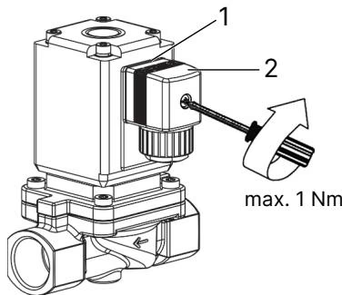
Electrical connection is established through the supplied DIN EN 175301-803 Form A cable plug. Assembly requires attention to electrical safety guidelines:
Alternating Current Armature Hazard
With alternating current (AC) coils, a mechanically seized or obstructed magnetic core prevents full magnetic pull-in. This causes coil current to remain at inrush levels, overheating the coil and leading to thermal failure. Ensure the medium is clean and the core area remains unobstructed.
Long Downtime Maintenance
When the valve remains energized or unactuated over prolonged system shutdowns, perform 1 to 2 switching cycles per day to maintain functional readiness.
| Fault | Possible Cause | Corrective Action |
|---|---|---|
| Valve does not actuate | Short circuit or coil winding interrupted | Check coil resistance and supply voltage; replace coil if burnt |
| Operating pressure out of permissible range | Verify operating pressure is within 0 to 16 bar | |
| Core or armature guide tube contaminated | Disassemble valve upper section and clean foreign matter | |
| Valve does not close | Valve interior or seat soiled | Inspect main diaphragm, seat face, and pilot orifice; clean contamination |
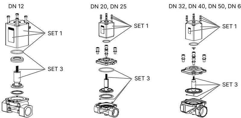
Spare parts can be ordered using the article number 48171 from the nameplate. Bürkert offers SET 1 (coil set) and SET 3 (wearing part set including diaphragm, springs, and elastomer seals). Only genuine manufacturer replacement parts must be used.
Type 0290 valves can be operated in combination with Type 2518 cable plugs (available unwired, with LED, varistor, or rectifier modules) and Type 1087 analogue or digital timing modules mounted directly to the Form A interface.
Explore similar products in our catalog


