

PN16

Burkert Type 6281 servo-assisted 2/2-way diaphragm valve. Features a vibration-resistant coil system, damped design, and optional Kick and Drop technology for neutral media up to 16 bar.
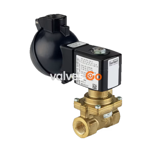
Burkert Type 6281 is a servo-assisted diaphragm valve designed for controlling, shutting off, and dosing neutral media with a viscosity of up to 21 mm²/s. A minimum differential pressure of 0.2 bar is always required for the valve to function. The standard brass body meets European drinking water requirements, and dezincification-resistant brass or stainless steel variants are available for specific market needs.
To reduce electrical power consumption during operation, coils with integrated Kick-and-Drop (KD) electronics featuring double coil technology are available. The valve features a vibration-resistant, centrally screwed coil system and a damped design for quiet closing.
| Feature | Specification |
|---|---|
| Orifice | DN 10 to DN 50 |
| Body Material | Brass acc. to DIN EN 50930-6, Stainless steel 1.4408 (CF8M) |
| Seal Material | NBR, EPDM, FKM |
| Duty Cycle | 100% continuous operation |
| Switching Time | Opening: 0.1...1.5 s, Closing: 0.2...4 s |
| Voltage Tolerance | ±10% |
| Degree of Protection | IP65 in accordance with DIN EN 60529/IEC 60529 with cable plug |
| Circuit Function | Description |
|---|---|
| A (NC) | 2/2-way solenoid valve, servo-controlled, normally closed |
| B (NO) | 2/2-way solenoid valve, servo-controlled, normally open |
Special Instructions for Circuit Function B
For valves with circuit function B (NO) featuring exhaust port G1/8 on the solenoid (CF05/MX62), the valve is open when there is no power. The medium also flows out via the exhaust port on the solenoid. These are primarily suitable for compressor relief.
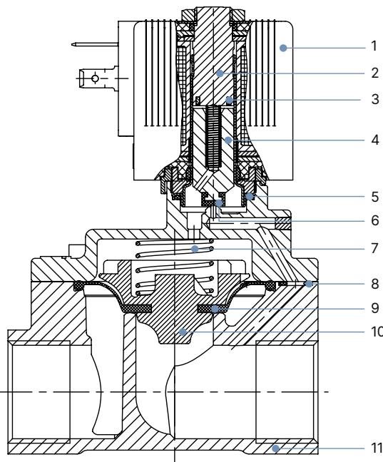
| No. | Element | Material |
|---|---|---|
| 1 | Coil | Polyamide or epoxy |
| 2 | Stopper | Stainless steel 1.4113 |
| 3 | Shading ring | Cu (brass variant), Ag (stainless steel variant) |
| 4 | Magnetic core | Stainless steel 1.4113 |
| 5 | O-ring | NBR, FKM, EPDM |
| 6 | Core seal | NBR, FKM, EPDM |
| 7 | Spring | Stainless steel 1.4310 |
| 8 | O-ring | NBR, FKM, EPDM |
| 9 | Diaphragm | NBR, FKM, EPDM |
| 10 | Diaphragm holder | PPSGF40 (DN 50: brass and stainless steel) |
| 11 | Valve body | Brass or stainless steel 1.4408 (CF8M) |
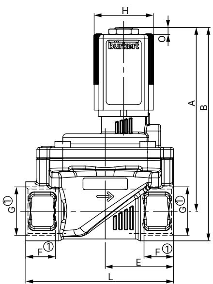
Dimensions in mm. The dimensions F1 and G1 apply to G thread.
| DN | A | B | C | D | E | G1 | L | SW |
|---|---|---|---|---|---|---|---|---|
| 10 | 83.1 | 94.1 | 32 | 44 | 22 | G 1/4, G 3/8 | 50 | 22 |
| 13 | 91.1 | 104.6 | 42 | 54.5 | 27.25 | G 3/8, G 1/2 | 58 | 27 |
| 20 | 99.6 | 115.6 | 60 | 74 | 37 | G 3/4 | 80 | 32 |
| 25 | 106.6 | 127.1 | 70 | 85 | 46 | G 1 | 95 | 41 |
| 40 | 120.1 | 145.1 | 99 | 114 | 61 | G 1 1/4, G 1 1/2 | 126 | 50 |
| 50 | 119.9 | 154.9 | 115 | 132 | 82 | G 2 | 164 | 70 |

The type label includes: (1) Type, (2) Circuit function, (3) Orifice, (4) Sealing material, (5) Body material, (6) PN, (7) Connection type, (8) Power, (9) Frequency, (10) Voltage, (11) Manufacture code, and (12) Article number.
Risk of injury from high pressure and electric shock
Installation Precautions
To manually operate the valve (code HA15/HA17), the hand lever must be turned to a vertical position below the solenoid. Do not over-rotate the hand lever. When the hand lever is actuated, the valve can no longer be switched electrically.
Explore similar products in our catalog


