

PN16

BURKERT 332773 (Type 6013) is a direct-acting 2/2-way normally closed plunger solenoid valve with brass body, NPT 1/4 ports, 3.0 mm orifice, 0-6 bar operating pressure, FKM seals, and 24 V DC coil.
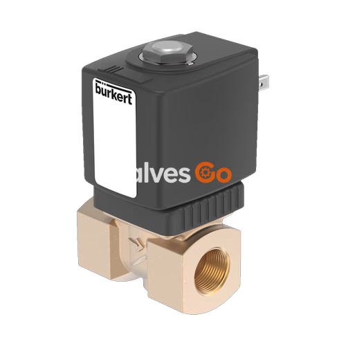
BURKERT 332773 (Type 6013) is a direct-acting 2/2-way plunger solenoid valve engineered for neutral gases, liquids, and technical vacuum across automated fluid systems. Designed with circuit function A (normally closed), the valve operates without pilot differential pressure from 0.00 bar up to 6.00 bar. It features a solid brass body, female NPT 1/4 process connections, a DN 3.0 mm orifice, and a rated water flow factor (Kv) of 0.23 m³/h. Fluid sealing is provided by high-grade FKM elastomer, ensuring operational integrity from -10 °C to +120 °C. The valve uses a vibration-proof bolted solenoid coil system running on 24 V DC with an 8 W continuous power rating and carries UL Listed approval according to UL 429.
In Type 6013 valves, the fixed core (stopper) and the core guide tube are welded together. This construction increases pressure tightness and mechanical stability while eliminating leak paths around the plunger guide sleeve. Fluid flows over the seat from inlet port 1 (P/NC) to outlet port 2 (A).
Scope of Delivery
Article 332773 is supplied complete with an enclosed Form A cable plug conforming to DIN EN 175301-803, providing an ingress rating of IP65 when correctly installed.
| Attribute | Specification Value |
|---|---|
| Article Number | 332773 |
| Model Series | Type 6013 |
| Circuit Function | A (2/2-way, normally closed) |
| Flow Direction | Over seat, inlet port 1 to outlet port 2 |
| Nominal Diameter (Orifice) | DN 3.0 mm (1/8") |
| Kv Value (Water) | 0.23 m³/h (measured at +20 °C, 1 bar Δp) |
| Operating Pressure Range | 0.00 to 6.00 bar (gas and liquid) |
| Port Connection | NPT 1/4 Internal Thread |
| Body Material | Brass |
| Seal Material | FKM (Fluor rubber) |
| Coil Operating Voltage | 24 V DC (±10% voltage tolerance) |
| Power Consumption | 8 W (9 W cold state at +20 °C) |
| Coil Size | Size 5 (32 mm width) |
| Switching Response Times | Opening: 20 ms, Closing: 30 ms |
| Medium Temperature Range | -10 °C to +120 °C |
| Ambient Temperature Range | -10 °C to +55 °C |
| Fluid Viscosity | Max. 21 mm²/s |
| Electrical Connection | DIN EN 175301-803 Form A plug pattern |
| Ingress Protection Rating | IP65 (with attached cable plug) |
| Duty Cycle | 100% ED continuous rating |
| Certification | UL Listed (UL 429) |
Type 6013 utilizes direct magnetic actuation where the plunger acts directly on the valve seat orifice. No minimum operating pressure differential is required for switching.

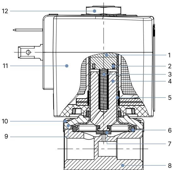
| Position No. | Component Element | Material |
|---|---|---|
| 1 | Stopper | Stainless steel 1.4105 / 430F |
| 2 | Shading Ring | Copper (Cu) for brass valve variant |
| 3 | Core Spring | Stainless steel 1.4310 / 301 |
| 4 | Magnetic Core (Armature) | Stainless steel 1.4105 / 430F |
| 5 | Core Guide Tube | Stainless steel 1.4303 / 305 / 308 (welded to stopper) |
| 6 | Housing Seal | FKM |
| 7 | Armature Seat Seal | FKM |
| 8 | Valve Body | Brass |
| 9 | Sub-base | Steel, surface finish thick-film passivated |
| 10 | Coil Cover | Polyamide (PA) |
| 11 | Solenoid Coil | Polyamide (Class B) or Epoxy (Class H) |
| 12 | Top Retaining Nut | Steel, surface finish thick-film passivated |

All dimensions are specified in millimeters (mm):
| Port Connection A | Overall Body Length B [mm] | Port Depth to Center C [mm] | Height Body Flange D [mm] | Thread Engagement G [mm] |
|---|---|---|---|---|
| G / NPT 1/8 | 32 | 20.8 | 32.6 | 8 |
| G / NPT 1/4 (Article 332773) | 46 | 26.8 | 49.0 | 12 |
| G / NPT 3/8 | 50 | 39.8 | 38.0 | 12 |
| Sub-base (SFB) | 32 | 14.3 | 32.6 | — |
| Coil Size | Coil Width E [mm] | Coil Depth F [mm] |
|---|---|---|
| Coil Size 5 (32 mm) | 32 | 45 |
| Coil Size 6 (40 mm) | 40 | 51 |
Type 6013 valves feature consistent dynamic performance across DC and AC variants. Values for circuit function A are detailed below:
| Orifice [mm] | Coil Power Rating [W] | Electrical Power Inrush AC [VA] | Electrical Power Hold AC [VA] | Coil Size | Opening Time [ms] | Closing Time [ms] |
|---|---|---|---|---|---|---|
| 2.0 | 8 W AC or 8 W DC (9 W) | 24 | 17 | 5 (32 mm) | 20 | 30 |
| 2.5 | 8 W AC or 8 W DC (9 W) | 24 | 17 | 5 (32 mm) | 20 | 30 |
| 3.0 (Article 332773) | 8 W AC or 8 W DC (9 W) | 24 | 17 | 5 (32 mm) | 20 | 30 |
| 3.0 | 10 W AC or 10 W DC (11 W) | 30 | 22 | 6 (40 mm) | 20 | 30 |
| 4.0 | 8 W AC or 8 W DC (9 W) | 24 | 17 | 5 (32 mm) | 20 | 30 |
| 4.0 | 10 W AC or 10 W DC (11 W) | 30 | 22 | 6 (40 mm) | 20 | 30 |
| 6.0 | 8 W AC or 8 W DC (9 W) | 24 | 17 | 5 (32 mm) | 20 | 30 |
| 6.0 | 10 W AC or 10 W DC (11 W) | 30 | 22 | 6 (40 mm) | 20 | 30 |
Values in brackets correspond to a cold coil temperature of +20 °C.
Mounting Orientation
The valve can be installed in any orientation. Mounting with the solenoid coil upright is recommended to minimize dirt accumulation inside the core guide tube.
Operating Restrictions
Do not operate beyond the 6.00 bar differential pressure limit. Media viscosity must remain below 21 mm²/s to avoid sluggish plunger movement and seal degradation.
According to safety documentation for Type 6013, the valve qualifies as a Type A element under IEC 61508. When implemented as the sole final element, it meets SIL 2 with HFT=0 or SIL 3 with HFT=1 in low demand safety-instrumented functions (SIF). Proof test intervals, partial valve stroke testing (PVST), and full valve stroke testing (FVST) should be scheduled based on system PFDavg calculations.
Explore similar products in our catalog


