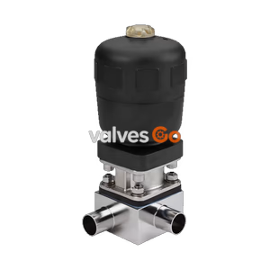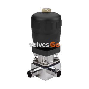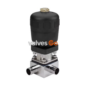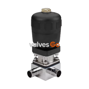
Type 2032

BURKERT 311678 Type 2104 is a pneumatic 3/2-way NC stainless steel T-diaphragm valve with DN 65 ASME BPE weld ends, advanced PTFE/EPDM diaphragm, 0-10 bar medium pressure, and integrated ELEMENT automation interface.
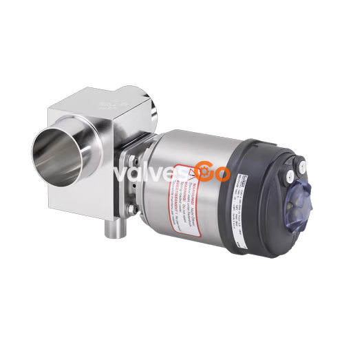
BURKERT 311678 (Type 2104) is a pneumatically operated 3/2-way stainless steel T-diaphragm valve designed for hygienic processing, sampling, and distribution in decentralised automation systems. The assembly consists of an externally controlled pneumatic piston actuator, an advanced PTFE/EPDM diaphragm, and a zero-deadleg T-valve body machined from solid 1.4435 / 316L block material. Operating under Control Function A (normally closed by spring force), the valve shuts off the branch weir at media pressures up to 10 bar (PN 16 / Class 150) using a 5.5 to 7.0 bar pneumatic pilot pressure signal.
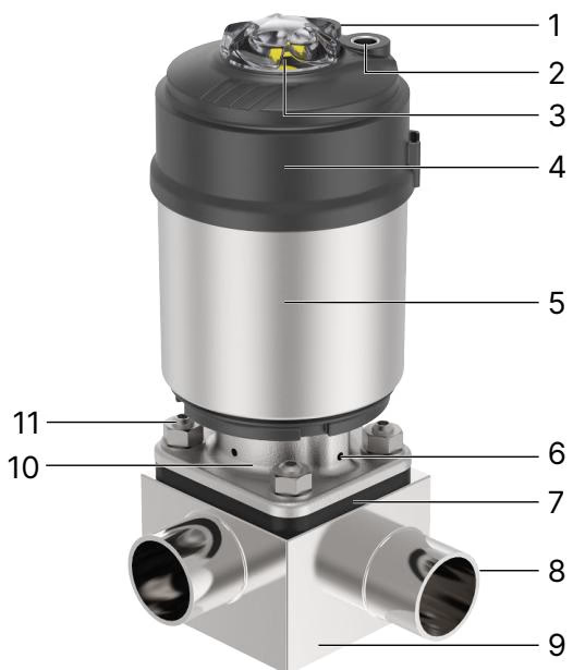
Designed for integration into the Bürkert ELEMENT architecture, the valve features internal pilot air routing and a 360° continuously rotatable interface. The wetted process body features ASME BPE / DIN 11866 Series C butt-weld ends with a main line nominal diameter of DN 65 (2 1/2", 63.5 mm OD) and a branch nominal diameter of DN 40 (1 1/2", 38.1 mm OD), delivering high flow capacity while fully supporting CIP and SIP cycles at temperatures up to 143 °C (and short-term steam sterilisation at 150 °C for 60 minutes).
| Parameter | Specification Details |
|---|---|
| Product Type | Type 2104 ELEMENT T-Diaphragm Valve |
| Article Number | 311678 |
| Circuit Function | 3/2-way, Control Function A (NC, normally closed by spring force) |
| Main Port Connection (Port 1) | Butt weld end DN 65 (2 1/2", 63.5 mm outer diameter, 60.2 mm inner diameter, 1.65 mm wall thickness) |
| Branch Port Connection (Port 2) | Butt weld end DN 40 (1 1/2", 38.10 mm outer diameter, 34.80 mm inner diameter, 1.65 mm wall thickness) |
| Applicable Pipe Standards | ASME BPE / DIN 11866 Series C |
| Diaphragm Size | Size 40 (40 mm body weir orifice) |
| Operating Pressure Range | 0.00 bar to 10.00 bar (PN 16 / ASME Class 150) |
| Pilot Pressure Range | 5.5 bar to 7.0 bar (push-in ∅ 6 mm ELEMENT interface) |
| Medium Temperature Range | -5 °C to +143 °C (steam sterilisation max. +150 °C for 60 min) |
| Ambient Temperature Range | -5 °C to +55 °C (-10 °C to +60 °C series range) |
| Pilot Air Fluid | Neutral gases, filtered instrument air |
| Enclosure Rating | IP65 / IP67, NEMA Type 4X |
| Documentation Included | EN 10204 3.1 inspection certificate, EN 10204 2.1 diaphragm certificate |
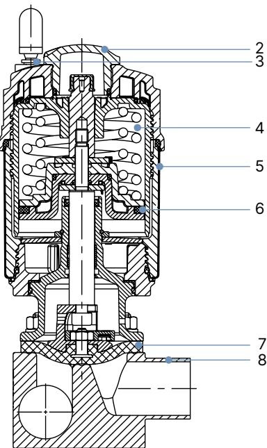
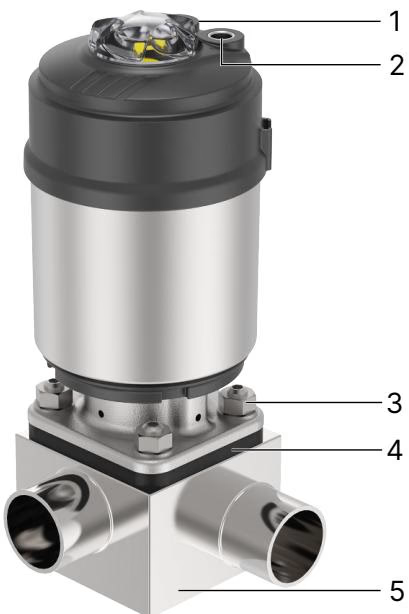
The Type 2104 ELEMENT valve pairs a block-machined stainless steel valve body with an autoclaved, chemical-resistant pneumatic actuator casing designed without external air tubing lines:
| Pos. | Component Part | Material Specification |
|---|---|---|
| 1 | Ground Terminal | Stainless steel 1.4301 / 1.4305 (for ATEX / IECEx variants) |
| 2 | Transparent Position Cap | Polysulfone (PSU) |
| 3 | Pilot Air Ports | Push-in connector Polypropylene (PP) ∅ 6 mm, G 1/8 stainless steel 1.4305 |
| 4 | Internal Actuator Housing | Polyphenylene sulphide (PPS) |
| 5 | Actuator Cover Envelope | Stainless steel 1.4561 (316Ti) |
| 6 | Piston Seal | Fluoroelastomer (FKM) |
| 7 | Diaphragm | Advanced PTFE with EPDM backing cushion (Code EU) |
| 8 | T-Valve Body | Stainless steel 1.4435 (DIN EN 10088) / 316L (ASME BPE Table MM-2.1.1) |
Wetted surfaces are finished to sanitary process standards: electropolished to Ra ≤ 0.38 µm (ASME BPE SF4 / DIN HE4) or mechanically polished to Ra ≤ 0.5 µm (ASME BPE SF1), with external surfaces finished to Ra ≤ 1.6 µm.
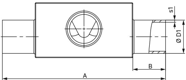
Dimensional layout for Type 2104 welded block T-bodies complies with ASME BPE and DIN 11866 Series C pipe geometry. Article 311678 features Diaphragm Size 40 with a DN 65 main line and DN 40 branch line (product combination key SODJ-SODH):
| Diaphragm Size | Port 1–Port 2 DN | ∅D1 [mm] | s1 [mm] | ∅D2 [mm] | s2 [mm] | A [mm] | B [mm] | C [mm] | E [mm] | F [mm] | G [mm] | H [mm] | I [mm] | Product Key |
|---|---|---|---|---|---|---|---|---|---|---|---|---|---|---|
| 40 | 40...40 | 38.10 | 1.65 | 38.10 | 1.65 | 152.0 | 25.0 | 99.6 | 25.0 | 121.0 | 58.0 | 35.0 | 6.4 | SODH-SODH |
| 40 | 50...40 | 50.80 | 1.65 | 38.10 | 1.65 | 162.0 | 30.0 | 101.6 | 30.0 | 131.0 | 72.0 | 43.0 | 14.4 | SODI-SODH |
| 40 (311678) | 65...40 | 63.50 | 1.65 | 38.10 | 1.65 | 162.0 | 30.0 | 107.9 | 30.0 | 143.0 | 85.0 | 50.0 | 21.4 | SODJ-SODH |
| 40 | 80...40 | 76.20 | 1.65 | 38.10 | 1.65 | 162.0 | 30.0 | 114.3 | 30.0 | 156.0 | 98.0 | 56.0 | 27.4 | SODK-SODH |
All dimensions are stated in millimetres. Port 1 outer diameter is 63.50 mm (2 1/2") with 1.65 mm wall thickness, while Port 2 outer diameter is 38.10 mm (1 1/2") with 1.65 mm wall thickness.
The ELEMENT design allows mounting of intelligent control modules directly onto the actuator interface without external air supply pipes:
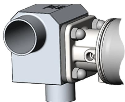
Type 2104 can be installed in any orientation, preferably with the actuator upright. When fitted into circular loop pipelines, specific drain angles should be maintained according to ASME BPE standards to guarantee complete gravity self-drainage.
Damage to Diaphragm or Actuator During Welding
Welding temperatures will degrade elastomer seals and actuator internals. Always unbolt and remove the actuator and diaphragm assembly from the body before orbital or manual welding of the block into the pipeline.
Leakage Detection Relief Bores
The diaphragm bonnet contains radial relief bores that vent fluid in the event of diaphragm rupture. Rotate the valve so that at least one relief bore points towards the lowest position to ensure immediate visual detection of seal leakage.
When reinstalling the actuator on Control Function A valves, follow the exact pressure sequence:
| Diaphragm Size | Tightening Torque for EPDM / FKM [Nm] | Tightening Torque for PTFE / Advanced PTFE / GYLON® [Nm] |
|---|---|---|
| 8 | 2.0 | 2.5 |
| 15 | 3.5 | 4.0 |
| 20 | 4.0 | 4.5 |
| 25 | 5.0 | 6.0 |
| 40 (311678) | 8.0 | 10.0 |
| 50 | 12.0 | 15.0 |
| 65 | 20.0 | 30.0 |
| 80 | 30.0 | 40.0 |
| 100 | 40.0 | 50.0 |
Torque tolerance is +10%. For Diaphragm Size 40 with advanced PTFE (EU), tighten bolts to exactly 10.0 Nm.
Diaphragms represent consumable components requiring routine inspection. For Diaphragm Size 40, the advanced PTFE diaphragm connects to the actuator compressor via an integrated bayonet catch. Rotate the diaphragm 90° to detach it from the compressor guide slot.
Switching Between Diaphragm Materials
When converting from a bayonet PTFE diaphragm to a threaded EPDM diaphragm on sizes ≥25, an adapter insert must be placed into the compressor. Conversely, remove this insert before mounting a bayonet PTFE diaphragm to prevent damage to the compressor assembly.
| Symptom | Probable Cause | Corrective Action |
|---|---|---|
| Actuator fails to switch | Pilot air connected to wrong port | Connect control pressure to pilot port 1 (CF A) |
| Actuator fails to switch | Pilot air pressure below 5.5 bar | Increase pilot pressure to 5.5–7.0 bar range |
| Valve seat leakage | Medium operating pressure exceeds 10 bar | Verify system operating pressure complies with specification |
| Valve seat leakage | Particulate entrapment or diaphragm wear | Disassemble, clean weir surface, or replace diaphragm |
| Reduced fluid flow rate | Diaphragm bulging due to thermal overstress | Replace diaphragm kit with genuine Bürkert spare part |
Explore similar products in our catalog