

PN16

BURKERT 307272 (Type 5404) servo-assisted 2/2-way piston solenoid valve. Steam variant NA07, G 1/2 internal thread, 1-12 bar pressure range, 110V 50Hz, PTFE seal, suitable for temperatures up to 160°C.
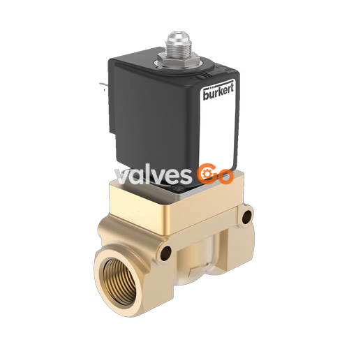
BURKERT 307272 (Type 5404) is a servo-assisted 2/2-way piston valve designed for demanding applications. A minimum differential pressure is required for the valve switching function. The solenoid coils are moulded with high-quality epoxy resin. In combination with a plug to DIN EN 175301-803 Form A, the valves satisfy degree of protection IP65. This specific model is configured as a steam variant (NA07) with a 13 mm orifice, suitable for temperatures up to +160 °C.
| Feature | Value |
|---|---|
| Seal material | PTFE seat seal and Graphite (steam variant) |
| Body material | Brass |
| Coil material | Epoxy resin |
| Orifice | DN 13 |
| Circuit function | A (Normally closed) |
| Thermal insulation class | Epoxy resin coil class H |
| Duty cycle | 100% continuous operation |
| Operating voltage | 110 V 50 Hz |
| Voltage tolerance | ±10% |
| Operating medium | Neutral gases and liquids (e.g., steam) |
| Medium temperature | -40 °C ... +160 °C |
| Ambient temperature | -10 °C ... +55 °C |
| Degree of protection | IP65 with cable plug Type 2518 |
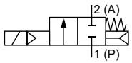
Circuit function A (CF A): 2/2-way solenoid valve, servo-controlled, normally closed.
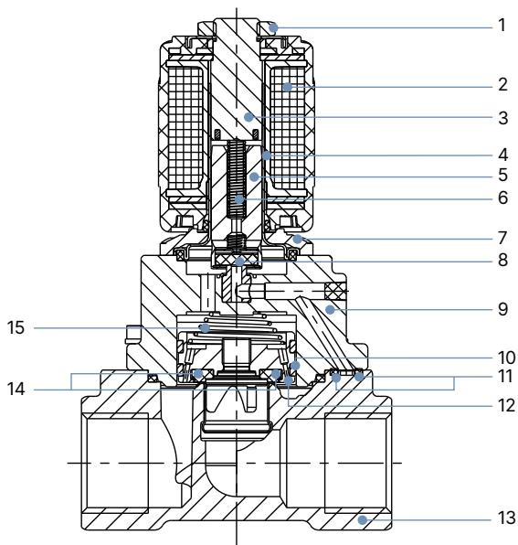
| No. | Element | Material |
|---|---|---|
| 1 | Nut | Steel (thick-film passivated according to RoHS) |
| 2 | Coil | Epoxy |
| 3 | Stopper | Stainless steel 1.4113/434 |
| 4 | Armature guide tube | Stainless steel 1.4303/305 |
| 5 | Plunger | Stainless steel 1.4113/434 |
| 6 | Spring | Stainless steel 1.4310/301 |
| 7 | Flange | Steel (thick-film passivated according to RoHS) |
| 8 | Plunger seal | PTFE |
| 9 | Cover | Brass |
| 10 | Piston ring | PTFE |
| 11 | O-ring | Graphite |
| 12 | Piston | Brass |
| 13 | Valve body | Brass |
| 14 | Piston seal | PTFE |
| 15 | Spring | Stainless steel 1.4310/301 |
INFO
Dimensions in mm. The dimensions D1 and F1 apply to G thread. The dimensions D2 and F2 apply to NPT thread. The dimensions D3 and F3 apply to Rc thread.
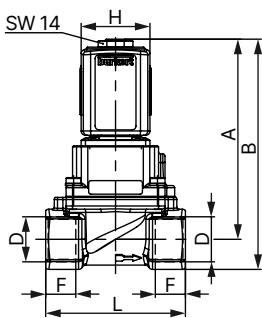
| Coil size | DN | A | B | G thread (D1) | G thread (F1) | NPT thread (D2) | NPT thread (F2) | Rc thread (D3) | Rc thread (F3) | E | L | SW | H | J | K |
|---|---|---|---|---|---|---|---|---|---|---|---|---|---|---|---|
| 5 | 13 | 93.1 | 107.1 | G 1/2 | 14 | NPT 1/2 | 13.7 | Rc 1/2 | 13.2 | 40 | 65 | 27 | 32 | 20.5 | 45 |
| 6 | 13 | 93.1 | 107.1 | G 1/2 | 14 | NPT 1/2 | 13.7 | Rc 1/2 | 13.2 | 40 | 65 | 27 | 40 | 23.5 | 51 |
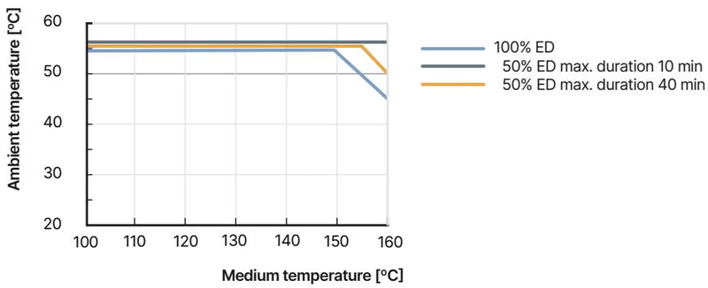
Temperature/duty cycle derating diagram for steam variant NA07
Risk of injury from high pressure and electric shock
Risk of burns/fire
Keep the device away from highly flammable substances and media and do not touch with bare hands if operated continuously.
Installation Position
As required, preferably with actuator upright. Install a dirt trap upstream of the valve inlet (≤ 500 μm).
Explore similar products in our catalog


