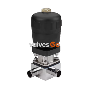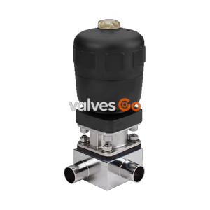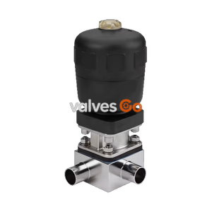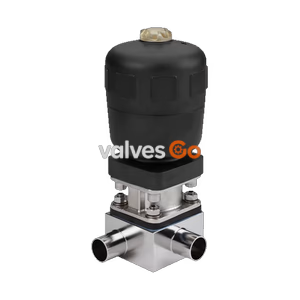
Type 2032

BURKERT 20131008 (Type 2032) is an externally piloted 3/2-way T-diaphragm valve with stainless steel block body, 1" ASME BPE weld ends, PPS actuator, and EPDM seal rated 0 to 10 bar, -10°C to 143°C.
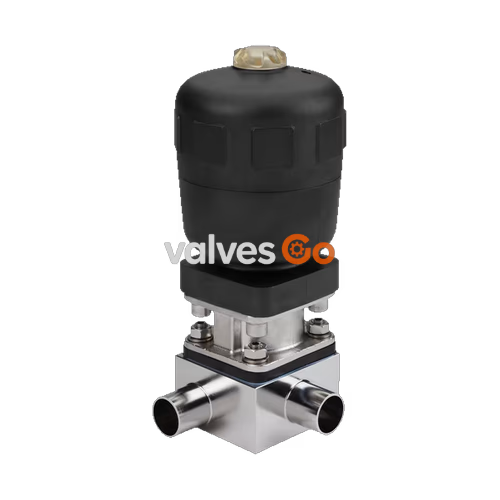
BURKERT 20131008 (Type 2032) is an externally piloted 3/2-way T-diaphragm valve designed for zero dead leg sampling, distribution, and drainage in ultra-pure and hygienic process systems. The unit integrates a pneumatically actuated piston drive, an EPDM high-temperature diaphragm, and a machined stainless steel block body with 1" ASME BPE welded ends. Configured in Control Function B (normally open by spring force), the valve remains open in its unpressurised state and closes upon pneumatic pilot actuation, delivering leak-tight shut-off across an operating pressure span from 0.00 to 10.00 bar.
Constructed from forged/block stainless steel 1.4435 (DIN EN 10088) / 316L (ASTM A479), the wetted interior is electropolished to Ra ≤ 0.38 µm (ASME BPE SF4 / DIN HE4). The valve complies with ASME BPE / DIN 11866 Series C piping standards (outer diameter 25.4 mm, wall thickness 1.65 mm). The autoclavable polyphenylene sulphide (PPS) actuator housing withstands ambient operating temperatures from +5 °C to +140 °C, supporting both CIP (clean-in-place) and SIP (sterilise-in-place) cycles up to +150 °C for 60 minutes.
| Specification Parameter | Value / Range |
|---|---|
| Article Number | 20131008 |
| Valve Type | Type 2032 (CLASSIC) |
| Fluidic Ports | 3 ports, 2 switching positions (3/2-way T-body) |
| Control Function | Control Function B (CF B) — normally open (NO) by spring force |
| Body Nominal Size | 20 mm |
| Port 1 Connection | Weld end 1" (DN 25), ASME BPE / DIN 11866 Series C |
| Pipe Dimensions | Outer Ø 25.4 mm (1.000"), Inner Ø 22.1 mm, Wall thickness 1.65 mm (0.065") |
| Body Material | Stainless steel block 1.4435 / 316L (BN2 on request) |
| Surface Roughness (Internal) | Ra ≤ 0.38 µm (electropolished, ASME BPE SF4 / DIN HE4) |
| Surface Roughness (External) | Ra ≤ 1.6 µm |
| Actuator Material | PPS (Polyphenylene sulphide), autoclavable |
| Actuator Piston Seal | FKM (Fluor rubber) |
| Diaphragm Material | EPDM high-temperature (AD code) |
| Operating Medium Pressure | 0.00 bar to 10.00 bar (gauge) |
| Nominal Pressure Rating | PN 16 (DIN EN 1333) / Class 150 (DIN EN 1759) |
| Pilot Control Pressure Range | 2.0 bar to 7.0 bar |
| Pilot Air Connection | G 1/4 internal thread |
| Medium Temperature Range | -10 °C to +143 °C (steam sterilisation max. +150 °C for 60 min) |
| Ambient Temperature Range | +5 °C to +140 °C |
| Certificates Included | EN 10204 3.1 inspection certificate, Factory certification 2.1 Membrane |
BURKERT 20131008 operates under Control Function B (CF B). Internal springs maintain the diaphragm in an open position relative to the valve seat when no pilot air is applied. Supplying compressed air (2.0 to 7.0 bar) to the upper pilot port forces the piston actuator downward against spring tension, pressing the EPDM diaphragm firmly onto the machined weir of the T-body to isolate the branch line.
INFO
Control Function B requires pilot air connection to the upper pneumatic port only. For optimal diaphragm service life, set the pilot pressure to the minimum pressure required to counteract medium line pressure according to operating pressure curves, rather than operating continuously at maximum pilot pressure.
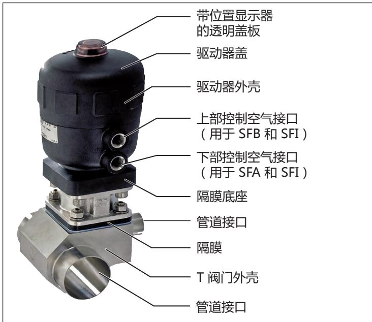
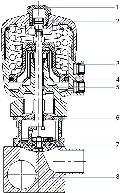
| Item No. | Component | Material |
|---|---|---|
| 1 | Transparent Position Indicator Cap | Polysulfone (PSU) |
| 2 | Actuator Cover Housing | Polyphenylene sulphide (PPS, autoclavable) |
| 3 | Pilot Air Ports | Stainless steel 1.4305 |
| 4 | Piston Seal | FKM (Fluor rubber) |
| 5 | Socket | Sinter metal |
| 6 | Actuator Interface / Bonnet | Stainless steel 1.4404 (316L) |
| 7 | Diaphragm | EPDM high-temperature (AD) |
| 8 | T-Valve Body | Stainless steel block material 1.4435 / 316L |
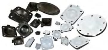
Diaphragms for Type 2032 meet stringent sanitary, pharmaceutical, and food-grade regulations:
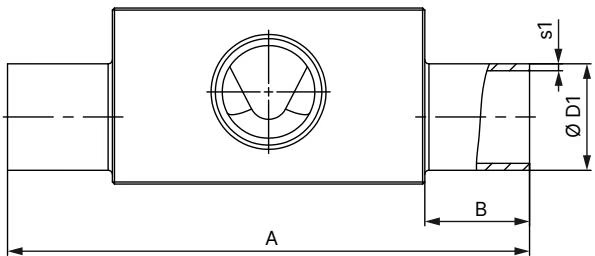
| Diaphragm Size | Port 1 – Port 2 DN | ØD1 [mm] | s1 [mm] | ØD2 [mm] | s2 [mm] | A [mm] | B [mm] | C [mm] | E [mm] | F [mm] | G [mm] | H [mm] | I [mm] | Product Key |
|---|---|---|---|---|---|---|---|---|---|---|---|---|---|---|
| 25 | 25 to 25 (1") | 25.40 | 1.65 | 25.40 | 1.65 | 124.5 | 25.0 | 74.8 | 25.0 | 95.0 | 42.0 | 26.0 | 6.0 | SODF-SODF |
| Diaphragm Size | Actuator Size Ø [mm] | Actuator Outer ØA [mm] | C Dimension [mm] | Pilot Port K | Height H [mm] | HM + MT85 Height [mm] |
|---|---|---|---|---|---|---|
| 25 | 63 (E) | 80 | 52 | G 1/4 | 170 | 266 |
| 25 | 80 (F) | 101 | 60 | G 1/4 | 190 | 286 |
BURKERT 20131008 features an operating medium pressure capability from 0 to 10 bar static pressure for EPDM seals. The pilot supply pressure must be regulated between 2.0 and 7.0 bar. For Control Function B with EPDM diaphragms, the required pilot closing pressure is governed by operating line pressure.
Temperature and Medium Limits
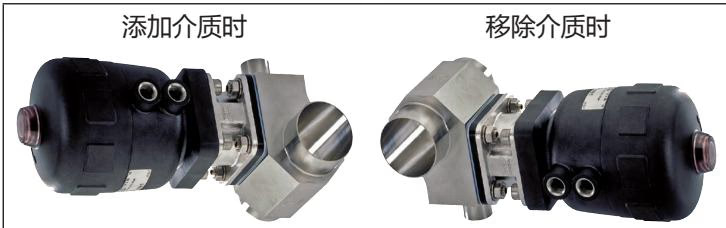
To ensure complete drainability and compliance with sanitary processing guidelines, follow these installation rules:
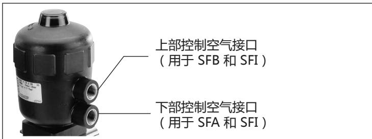
For Control Function B, connect clean, dry control air to the upper pilot air connection (G 1/4). In aggressive or washdown atmospheres, vent the lower port through tubing to a neutral area.
Routine maintenance involves checking the bonnet weep hole for medium leakage and examining the diaphragm for mechanical fatigue after 100,000 switching cycles or after aggressive steam sterilisation.
| Diaphragm Size (DN) | Tightening Torque for Block Body (VS) — EPDM / FKM [Nm] | Tightening Torque for Block Body (VS) — PTFE / GYLON [Nm] |
|---|---|---|
| 8 | 2.0 | 2.5 |
| 15 | 3.5 | 4.0 |
| 20 | 4.0 | 4.5 |
| 25 | 5.0 | 6.0 |
| 32 | 6.0 | 8.0 |
| 40 | 8.0 | 10.0 |
| 50 | 12.0 | 15.0 |
| 65 | 20.0 | 30.0 |
Tightening Tolerance
Tightening torque tolerance across all body bolts is +10%. Retighten bolts crosswise after the first operational steam sterilisation cycle to compensate for elastomer relaxation.
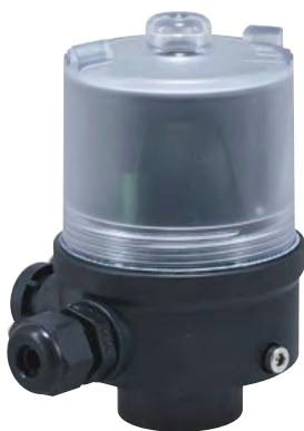
BURKERT 20131008 combines directly with Type 8697 pneumatic control and electrical position feedback units (actuator sizes Ø 40 to 225 mm). The Type 8697 features an IP65/IP67 chemically resistant enclosure, integrated optical LED indicators, and mechanical or inductive limit switches for automated plant monitoring. Combining the Type 2032 valve with Type 8697 forms the factory-tested on/off valve system Type 8801-TA.
Explore similar products in our catalog