Lift Type

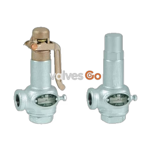
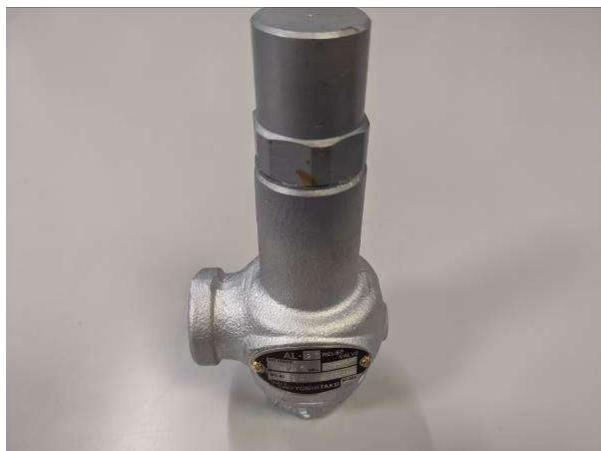
Yoshitake AL-27 closed-type safety relief valve with dashpot structure for heavy pulsation. For cold/hot water and oil, 0.05-1.6 MPa, up to 120°C.
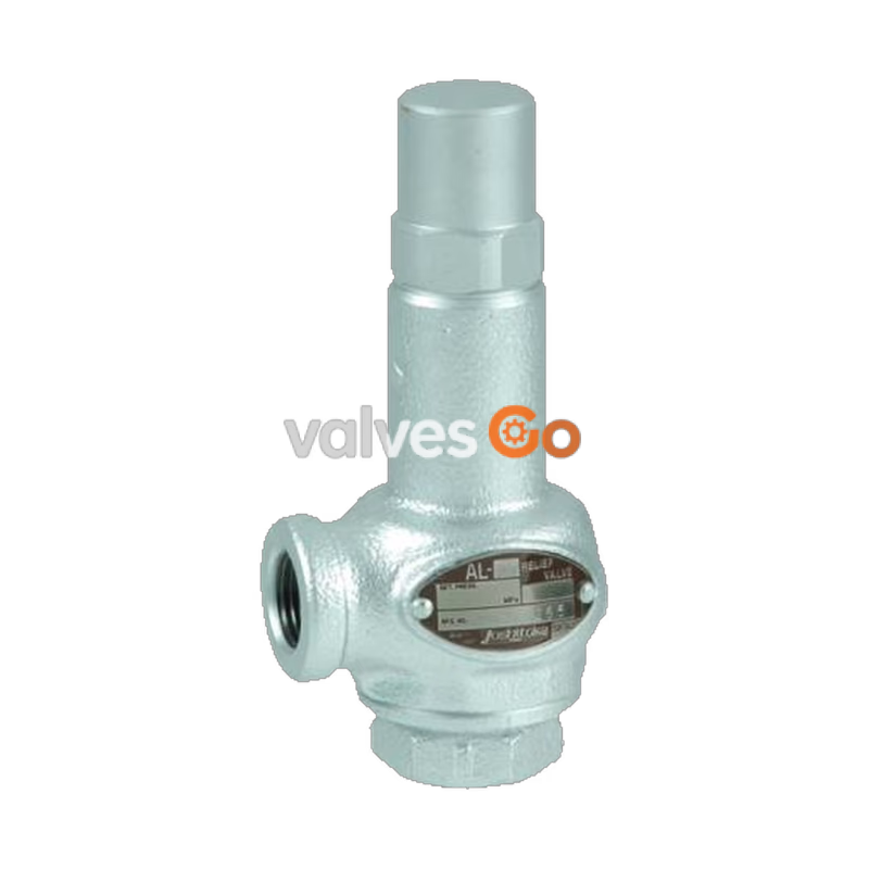
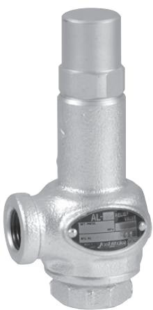
Yoshitake AL-27 is a closed-type safety relief valve designed for pressure control in pump systems where large pressure pulsation or fluctuation occurs. Featuring a unique dashpot structure, it prevents chattering and hunting, making it remarkably effective for lines with heavy pulsation. It maintains stable operation against back pressure changes produced during continuous blow and is suitable for cold and hot water, oil, and other non-dangerous fluids.
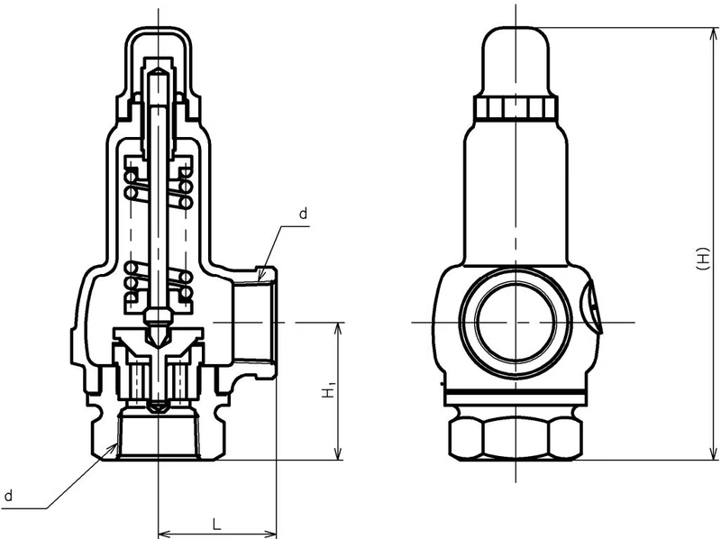
| Nominal Size | d | L (mm) | H1 (mm) | H (mm) | Weight (kg) |
|---|---|---|---|---|---|
| 15A | Rc 1/2 | 40 | 40 | 143 | 0.9 |
| 20A | Rc 3/4 | 45 | 50 | 162 | 1.3 |
| 25A | Rc 1 | 50 | 60 | 182 | 1.7 |
| 32A | Rc 1-1/4 | 60 | 70 | 220 | 2.9 |
| 40A | Rc 1-1/2 | 65 | 75 | 238 | 3.9 |
| 50A | Rc 2 | 80 | 85 | 272 | 6.4 |
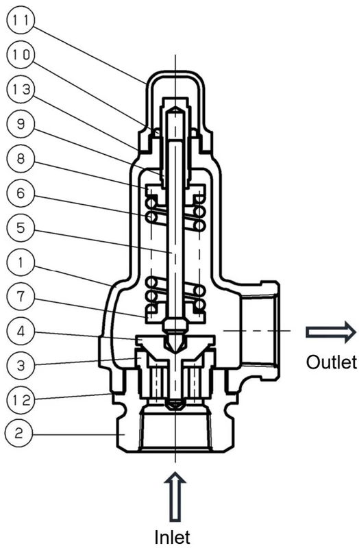
| No | Part Name | No | Part Name |
|---|---|---|---|
| 1 | Spring case | 8 | Spring plate |
| 2 | Body | 9 | Adjusting screw |
| 3 | Valve seat | 10 | Lock nut |
| 4 | Valve | 11 | Cap |
| 5 | Spindle | 12 | Gasket |
| 6 | Spring | 13 | Gasket |
| 7 | Spring plate |
As the inlet pressure approaches the set pressure, the force of the fluid pushing up the valve approaches the force of the spring pressing down the valve. When the inlet pressure increases further, the valve opens and discharges the fluid. The valve lift changes responding to the inlet pressure and controls it.
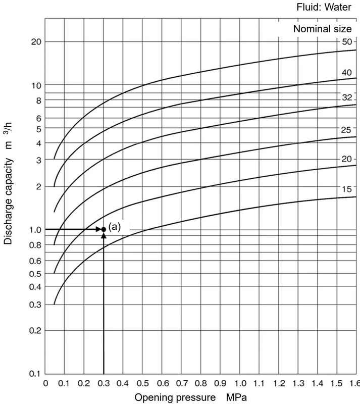
When selecting the nominal size for an opening pressure of 0.3 MPa and a discharge capacity of 1.0 m³/h, find the intersection point of the opening pressure of 0.3 MPa and the discharge capacity of 1.0 m³/h. If the intersection point lies between the nominal sizes 15A and 20A, select the larger one, 20A.
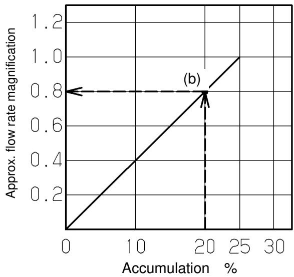
Accumulation: 25% (m³/h)
| Nominal size | 0.05 MPa | 0.1 MPa | 0.2 MPa | 0.3 MPa | 0.4 MPa | 0.5 MPa | 0.6 MPa | 0.7 MPa |
|---|---|---|---|---|---|---|---|---|
| 15A | 0.30 | 0.42 | 0.60 | 0.74 | 0.85 | 0.95 | 1.04 | 1.13 |
| 20A | 0.49 | 0.69 | 0.98 | 1.20 | 1.39 | 1.55 | 1.70 | 1.84 |
| 25A | 0.77 | 1.08 | 1.54 | 1.88 | 2.17 | 2.43 | 2.66 | 2.88 |
| 32A | 1.26 | 1.78 | 2.52 | 3.09 | 3.57 | 3.99 | 4.37 | 4.72 |
| 40A | 1.98 | 2.79 | 3.95 | 4.84 | 5.59 | 6.25 | 6.85 | 7.40 |
| 50A | 3.09 | 4.37 | 6.18 | 7.57 | 8.74 | 9.77 | 10.70 | 11.56 |
| Nominal size | 1.1 MPa | 1.2 MPa | 1.3 MPa | 1.4 MPa | 1.5 MPa | 1.6 MPa |
|---|---|---|---|---|---|---|
| 15A | 1.42 | 1.48 | 1.54 | 1.60 | 1.65 | 1.71 |
| 20A | 2.30 | 2.41 | 2.51 | 2.60 | 2.69 | 2.78 |
| 25A | 3.61 | 3.77 | 3.92 | 4.07 | 4.21 | 4.35 |
| 32A | 5.92 | 6.18 | 6.43 | 6.67 | 6.91 | 7.14 |
| 40A | 9.29 | 9.70 | 10.10 | 10.48 | 10.85 | 11.21 |
| 50A | 14.50 | 15.15 | 15.76 | 16.36 | 16.93 | 17.49 |
DANGER
WARNING
::: caution
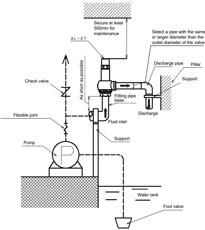
WARNING
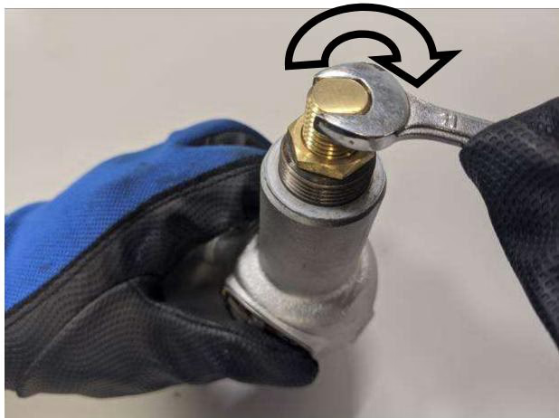
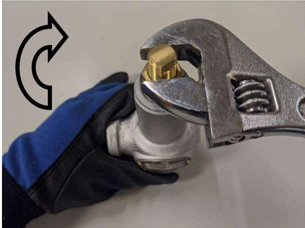
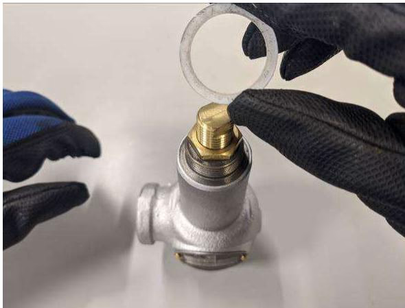
To adjust the set pressure, remove the cap, make a 1/4 to 1/3 turn of the adjusting screw slowly while checking the pressure gauge, and check the operation each time after turning the adjusting screw. Be careful not to overturn or the fluid may suddenly blow out. The fluid leaks from the thread of the adjusting screw while adjusting.
| Nominal size | Spring A | Spring B | Spring C | Spring D | Spring E |
|---|---|---|---|---|---|
| 15-50A | 0.05 up to 0.2 | Over 0.2 up to 0.4 | Over 0.4 up to 0.65 | Over 0.65 up to 1.0 | Over 1.0 up to 1.6 |
When a set pressure is not specified, confirm if the set pressure range is proper by checking the alphabet punched on the edge of the screwed connection.
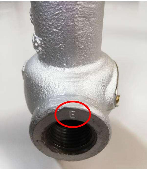
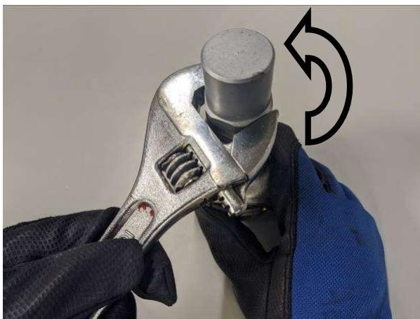
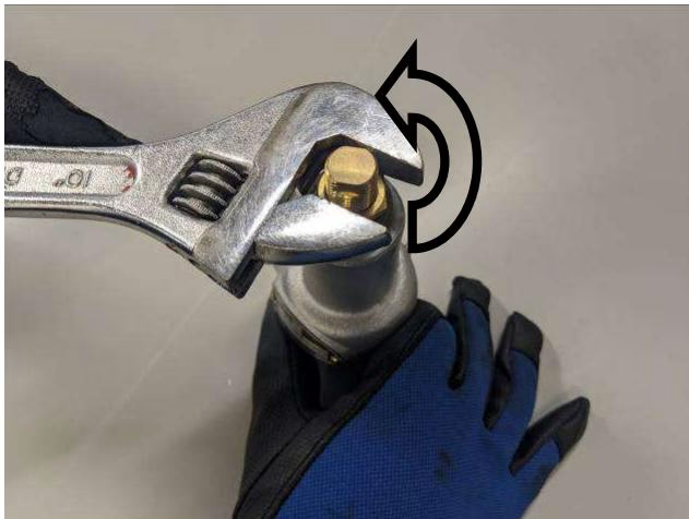
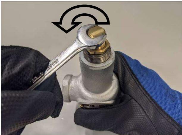
To increase the set pressure, make a 1/4 to 1/3 turn of the adjusting screw clockwise slowly by a spanner or a wrench. Check the operation of the product after each turn.
Yoshitake Safety Valves / Relief Valves
AF and AL series safety and relief valves for overpressure protection of steam, water, and air equipment.
Explore similar products in our catalog