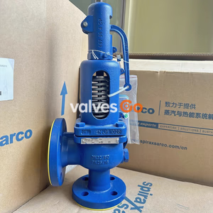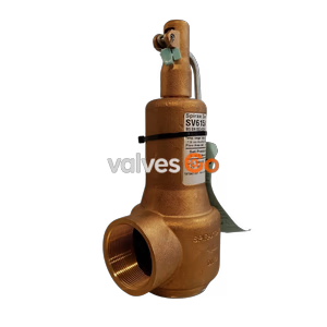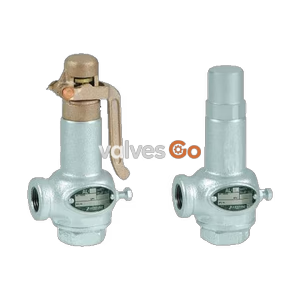
Lift Type

Yoshitake AL-24 and AL-24F are lift type safety relief valves featuring a bronze body, stainless steel seat, and diaphragm structure for reliable, leak-free operation in water and oil.
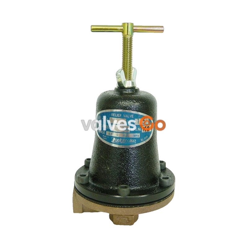
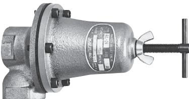
Yoshitake AL-24 and AL-24F are lift type safety relief valves designed with a diaphragm structure that eliminates sliding parts, ensuring highly reliable and non-leakage operation. The valve case is made of bronze, paired with a stainless steel valve seat, which provides excellent rust resistance. These valves offer a wide set pressure range from 0.1 to 0.7 MPa adjustable via a single spring, using a handle-type adjusting screw and a butterfly lock nut for ease of use. They provide smooth opening and closing even under continuous operation, maintaining stable flow relief from small to large capacities. They can be installed in any direction, horizontally or vertically.
| Model | AL-24 | AL-24F |
|---|---|---|
| Application | Cold and hot water | Cold and hot water, Oil, Other non-dangerous fluids |
| Working pressure | 0.1–0.7 MPa (*1) | 0.1–0.7 MPa (*1) |
| Maximum temperature | 60°C | 120°C |
| Valve case | Bronze (*2) | Bronze (*2) |
| Valve | NBR | FKM |
| Valve seat | Stainless steel | Stainless steel |
| Diaphragm | EPDM | FKM |
| Connection | JIS Rc screwed | JIS Rc screwed |
Notes
*1: Available with working pressure between 0.05 MPa and 0.1 MPa. *2: Available with NPb-treated.
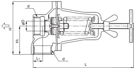
| Nominal size | d | L | L1 | H | H1 | D | Weight (kg) |
|---|---|---|---|---|---|---|---|
| 15A | Rc 1/2 | 180.5 | 20.5 | 91 | 46 | 15 | 1.4 |
| 20A | Rc 3/4 | 181.5 | 18.5 | 92 | 47 | 15 | 1.4 |
| 25A | Rc 1 | 187.5 | 17.5 | 97 | 52 | 18.2 | 1.6 |
Set pressure range 0.1 to 0.7 MPa (accumulation 25%)(Unit: m³/h)
| Nominal size | 0.10 | 0.15 | 0.20 | 0.25 | 0.30 | 0.35 | 0.40 | 0.45 | 0.50 | 0.55 | 0.60 | 0.65 | 0.70 |
|---|---|---|---|---|---|---|---|---|---|---|---|---|---|
| 15A | 0.31 | 0.38 | 0.44 | 0.49 | 0.54 | 0.58 | 0.63 | 0.66 | 0.70 | 0.73 | 0.77 | 0.80 | 0.83 |
| 20A | 0.31 | 0.38 | 0.44 | 0.49 | 0.54 | 0.58 | 0.63 | 0.66 | 0.70 | 0.73 | 0.77 | 0.80 | 0.83 |
| 25A | 0.46 | 0.56 | 0.65 | 0.73 | 0.80 | 0.86 | 0.92 | 0.98 | 1.03 | 1.08 | 1.13 | 1.18 | 1.22 |
Set pressure range 0.05 to 0.1 MPa (accumulation 25%)(Unit: m³/h)
| Nominal size | 0.05 | 0.06 | 0.07 | 0.08 | 0.09 | 0.10 |
|---|---|---|---|---|---|---|
| 15A | 1.27 | 1.39 | 1.50 | 1.61 | 1.70 | 1.80 |
| 20A | 1.27 | 1.39 | 1.50 | 1.61 | 1.70 | 1.80 |
| 25A | 1.87 | 2.05 | 2.21 | 2.37 | 2.51 | 2.65 |
V = (A × K × 12.4) / √(G / P)
e = D/40e = D/7A = π × D × e)INFO
Viscosity is calculated from the formula for viscosity correction.
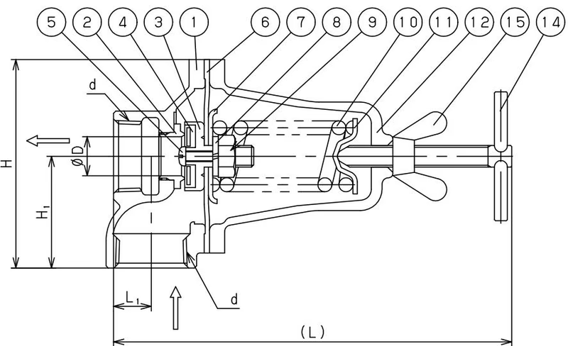
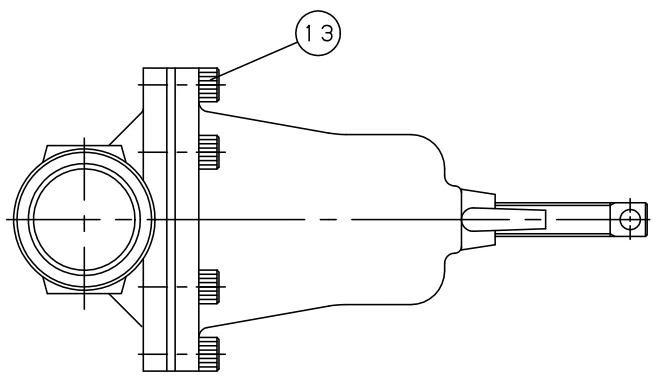
| No. | Part Name | Material |
|---|---|---|
| 15 | Wing Nut | Steel |
| 14 | Adjusting Screw | Steel |
| 13 | Bolt | Steel |
| 12 | Spring Cover | Cast Iron (FC200) |
| 11 | Spring Plate | Carbon Steel (SPC) |
| 10 | Spring | Piano Wire (SWP) |
| 9 | Nut | Brass (C3604) |
| 8 | Spring Washer | Steel |
| 7 | Diaphragm Shell | Carbon Steel (SPC) |
Yoshitake Safety Valves / Relief Valves
AF and AL series safety and relief valves for overpressure protection of steam, water, and air equipment.
Explore similar products in our catalog