Repairable

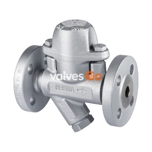
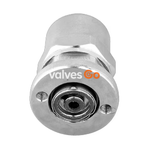
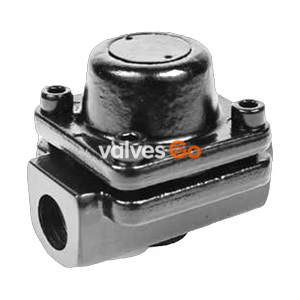
TLV L21S and L32S balanced pressure thermostatic steam traps feature a fail-open design and fixed subcooling. Suitable for tracer lines, dryers, and heaters up to 3.2 MPaG.
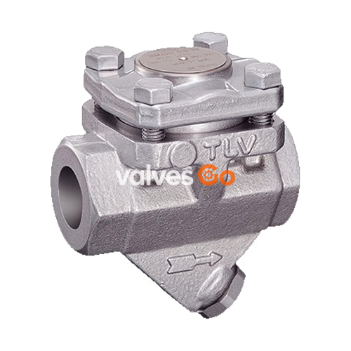
TLV L21S and L32S are balanced pressure thermostatic steam traps with a "fail open" design. The L21SC and L32SC models include an internal check valve. They can be used without adjustment for medium capacity applications and pressures up to 2.1 or 3.2 MPaG (300 or 450 psig). These models are suitable for steam-using equipment that discharges condensate at temperatures slightly below saturation temperature, such as tracer lines and light process equipment.
WARNING
To avoid malfunctions, product damage, accidents or serious injury, install properly and DO NOT use this product outside the specification range. Local regulations may restrict the use of this product to below the conditions quoted.
| Model | L21S / L21SC | L32S / L32SC |
|---|---|---|
| Material | Carbon Steel / Stainless Steel | Carbon Steel / Stainless Steel |
| Connection | Screwed, Socket Welded, Flanged | Screwed, Flanged |
| Size (mm) | DN 15, 20, 25 | DN 15, 20, 25 |
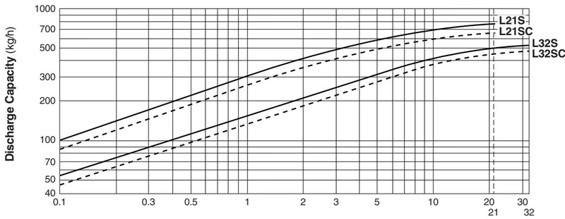
| Max. Operating Pressure (PMO) | 2.1 MPaG | 3.2 MPaG |
| Min. Operating Pressure | 0.01 MPaG | 0.01 MPaG |
| Maximum Back Pressure | 90% of inlet pressure | 90% of inlet pressure |
| Type of X-element | C6 | C6 |
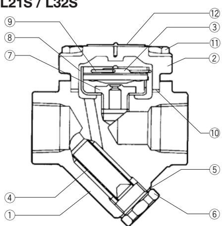
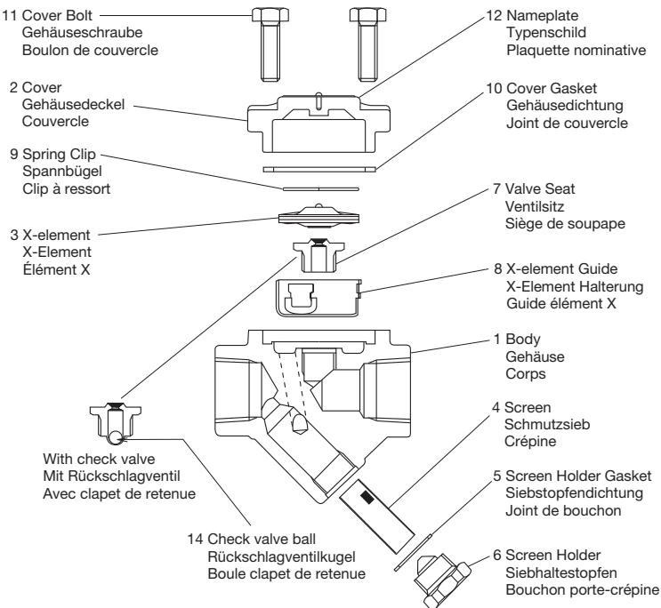
| Problem | Cause | Remedy |
|---|---|---|
| No condensate is discharged (blocked) or discharge is poor | X-element is stuck to the valve seat | Clean |
| Valve seat is clogged | Clean | |
| Screen is clogged with rust or scale | Clean | |
| Trap operating pressure exceeds maximum specified operating pressure | Study inlet pressure | |
| Steam leakage or blow-off | Valve closure is obstructed by rust, etc. | Clean (inspect screen as well) |
| X-element is worn or damaged | Replace X-element | |
| Valve seat is worn or damaged | Replace valve seat or cover | |
| Leakage from other location | Cover is loose or gaskets are worn or damaged | Tighten cover or replace gasket |
Explore similar products in our catalog