PN25

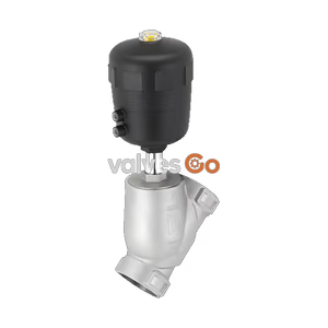
Burkert 377777 Type 2101 pneumatically operated 2/2-way globe valve. Features stainless steel body, PTFE seal, DN 50 flange connection, and handles pressures up to 12 bar and temperatures up to 185°C.
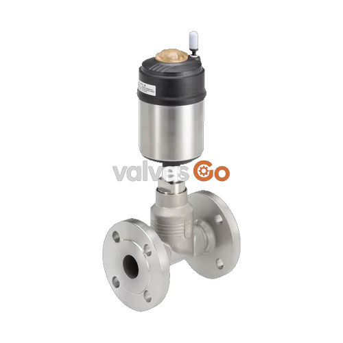
Burkert 377777 Type 2101 is a pneumatically operated 2/2-way globe valve ELEMENT optimized for decentralized process automation. It meets practical requirements even under difficult operating conditions. Its unique design allows easy integration of automation units in all expansion stages, from electrical/optical position feedback to pneumatic control and integrated fieldbus interface. Maximum service life and tightness are achieved by the proven self-adjusting v-seal packing gland. The highly integrated system of valve and automation unit is characterized by its compact and smooth design, integrated pilot air ducts, protection classes IP65/67, NEMA Type 4X, and high resistance to chemicals.
| Feature | Specification |
|---|---|
| Design | Globe valve |
| Safety setting in case of power failure | Normally closed (control function A) |
| Flow direction | Against closing direction (below seat), with closing direction (above seat) |
| Operating pressure | 0 bar(g)...12 bar(g) (for SKU 377777) |
| Nominal pressure | PN 25 (DIN EN 1333) |
| Pilot pressure | 2.7 bar(g)...7.0 bar(g) |
| Seat leakage | Leakage rate A (DIN EN 12266-1), seat seal PTFE, test medium air |
| Medium temperature | -10 °C...+185 °C |
| Ambient temperature | -10 °C...+100 °C |
| Degree of protection | IP65/67 |
| Installation position | As required, preferably with actuator in upright position |
The globe valve consists of a pneumatically actuated piston actuator and a 2-way body. The actuator is made from polyphenylene sulphide (PPS) or stainless steel.
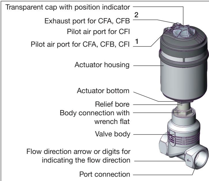
Depending on the variant, the valve is closed against the medium flow either with spring force (control function A, CFA) or pilot pressure (control function B or I, CFB or CFI). As the medium is present under the swivel plate, the operating pressure contributes to the opening of the valve.

Valve leak if there is too little minimum pilot pressure or high operating pressure!
Minimum pilot pressure for CFB and CFI that is too low, or failing to meet the permitted operating pressure, can cause a leak in the valve seat. Adhere to minimum pilot pressure and do not exceed the operating pressure.
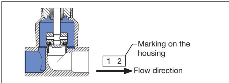
The valve is closed with the medium flow via spring force (control function A, CFA). Because the operating pressure is above the swivel plate, it helps the valve close and also contributes to sealing the valve seat. The valve opens via pilot pressure.
Risk of injury from pressure surge.
A pressure surge could cause lines and the device to burst. Because of the risk of pressure surge, valves with the flow direction above the seat must not be used for fluid media.
| Symbol | Description |
|---|---|
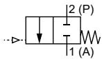 | Control function A (CF A) Pneumatically operated 2/2-way on/off valve Flow direction below seat Normally closed by spring force |
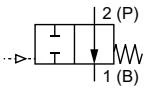 | Control function B (CF B) Pneumatically operated 2/2-way on/off valve Flow direction below seat Normally opened by spring force |
| No. | Element | Material |
|---|---|---|
| 4 | Actuator cover | PPS |
| 5 | Actuator casing | Stainless steel 1.4561 (316Ti) |
| 6 | Piston seal | FKM |
| 9 | Spindle packing | PTFE V-Rings (filled), with spring compensation |
| 10 | Spindle | Stainless steel 1.4401 (316)/1.4404 (316L) |
| 12 | Body seal | Graphite, PTFE (option) |
| 13 | Swivel plate | Stainless steel 1.4401 (316)/1.4404 (316L) |
| 14 | Seat seal | PTFE, PEEK (option) |
| 16 | Valve body | Stainless steel 316L / CF3M |
Temperature Ranges
| Actuator size [mm] | Actuator material | Medium temperature [°C] (PTFE seat seal) | Environment [°C] |
|---|---|---|---|
| ø 50, ø 70, ø 90, ø 130 | PPS | -10...+185 | -10...+100 |
| ø 225 | Stainless steel | -10...+185 | -10...+100 |
Pressure Ranges
| Actuator size [mm] | Maximum pilot pressure |
|---|---|
| ø 50, ø 70, ø 90 | 10 bar |
| ø 130 | 7 bar |
| ø 225, CFA | 7 bar |
| ø 225, CFB | 5 bar |
Dirt trap for devices with approval according to DIN EN 161
According to DIN EN 161 "Automatic shut-off valves for gas burners and gas appliances", a dirt trap must be installed upstream of the valve. The dirt trap must prevent the penetration of a 1 mm test pin.
Explore similar products in our catalog