PN25

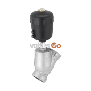
Burkert 368499 Type 2100 pneumatically operated 2/2-way angle seat valve. Features a stainless steel body, weld end connection, PTFE seal, and handles pressures up to 10 bar.
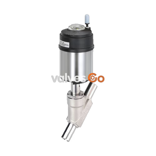
Burkert 368499 Type 2100 is a pneumatically operated 2/2-way angle seat valve optimized for decentralized process automation. The device controls the flow of liquid or gaseous media, including water, alcohols, oils, fuels, hydraulic fluids, saline solutions, lyes, organic solvents, vapor, and neutral gases. Maximum service life and tightness are achieved by the self-adjusting V-seal packing gland. The highly integrated system features a compact design, integrated pilot air ducts, IP65/67 protection, and high resistance to chemicals.
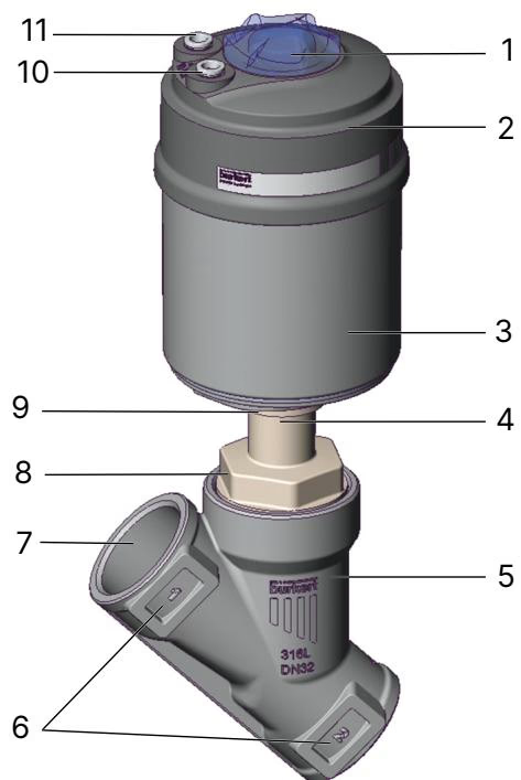
The 368499 model operates with Control function A (CF A). It is a pneumatically actuated 2/2-way on/off valve that is normally closed by spring force in the rest position.
For liquid media, gases, and vapors, the flow direction must be below the seat. As the medium is present under the swivel plate, the operating pressure contributes to the opening of the valve.
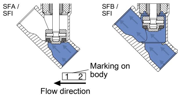
WARNING
Leaking valve seat with flow direction below seat If the pilot pressure is too low or the operating pressure is too high, the valve seat may leak. Comply with the minimum control pressure (5 bar) and the maximum operating pressure (10 bar) values.
| Element | Material |
|---|---|
| Actuator cover | PPS |
| Actuator casing | Stainless steel 1.4561 (316Ti) |
| Piston seal | FKM |
| Spring | Stainless steel 1.4310 |
| Packing gland | PTFE V-Rings (filled), with spring compensation |
| Spindle | Stainless steel 1.4401 (316)/1.4404 (316L) |
| Spindle guide | PEEK |
| Body seal | Graphite |
| Swivel plate | Stainless steel 1.4401 (316)/1.4404 (316L) |
| Seat seal | PTFE |
| Valve body | Stainless steel CF3M |
INFO
The lubricants for the packing gland and actuator are classified according to NSF H1.
The following fluidic and performance data applies specifically to the DN 50 configuration with Actuator size 90 (N) and PTFE seat seal.
| Property | Value |
|---|---|
| Nominal diameter | DN 50 |
| Actuator size ∅ | 90 (N) |
| Kv value (water) | 55 m³/h |
| Pilot pressure min. | 5.0 bar(g) |
| Operating pressure max. | 10 bar(g) |
| Medium temperature | -10 °C to +185 °C |
| Ambient temperature | -10 °C to +100 °C |
| Nominal pressure | PN 25 (DIN EN 1333) |
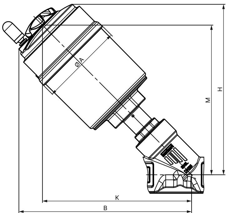
| Nominal diameter | Actuator size ∅ | ∅ A [mm] | B [mm] | H [mm] | K/M [mm] |
|---|---|---|---|---|---|
| DN 50 | 90 (N) | 120 | 262 | 261 | 236 |
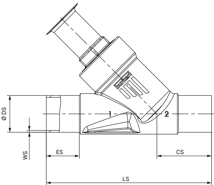
| Nominal diameter | Standard | ES [mm] | CS [mm] | LS [mm] | ∅ DS [mm] | WS [mm] |
|---|---|---|---|---|---|---|
| DN 50 | DIN EN ISO 1127 / ISO 4200 / DIN 11866 series B | 26 | 50 | 175 | 60.3 | 2.0 |
The device is suitable for use as category 2 equipment, non-electrical production equipment (structural safety) in zones 1/21 and 2/22.
Approvals:
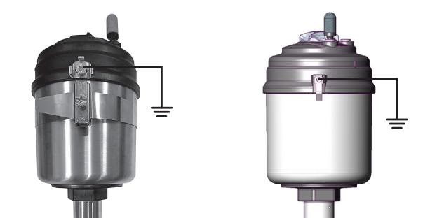
DANGER
Explosion hazard due to electrostatic charge! If statically charged devices or persons discharge suddenly, there is an explosion risk in the potentially explosive area.
Explore similar products in our catalog