Up to 99.8% Efficiency

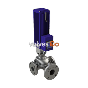
BURKERT 362825 (Type 3361) is a 24 V DC electromotive globe control valve with G 3/8 port, seat size 6 mm, PEEK seal, 1300 N AG2 actuator, SAFEPOS energy-pack, and display.
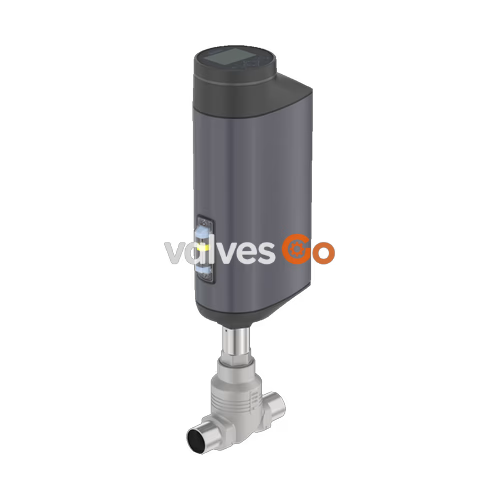
BURKERT 362825 (Type 3361) is an electromotive 2-way globe control valve engineered for continuous, high-precision modulation in demanding process conditions. Driven by a brushless DC motor with a precision ball screw, the unit delivers a positioning speed of 6 mm/s with a dead band of ±0.1%, compensating for process disturbances without pressure transfer from the pipeline back to the valve stem. Configured under article number 362825, this unit features a cast stainless steel CF3M valve body with G 3/8 internal thread (DN 10), an orifice seat diameter of 6 mm (1/4"), and a replaceable PEEK seat seal providing Class VI tight shut-off in accordance with DIN EN 60534-4 up to 25 bar(g).
The assembly includes the AG2 electromotive linear actuator delivering 1,300 N of positioning force, paired with an integrated electrical energy storage unit (SAFEPOS energy-pack) configured to close the valve automatically upon line power failure. Operator configuration and monitoring are supported locally via an integrated rugged display with push buttons and an optical 360° multi-colour LED status ring, as well as digitally through the Bürkert system bus (büS / CANopen) service interface. The unit conforms to EC Regulation 1935/2004 for wetted parts and carries explosion protection certifications for ATEX and IECEx Zone 2/22 (Category 3).
| Specification Parameter | Value / Characteristic |
|---|---|
| Valve Type | Type 3361 electromotive globe control valve |
| Article Number | 362825 |
| Port Connection Size | G 3/8 female thread (DIN ISO 228-1), nominal diameter DN 10 |
| Nominal Seat Diameter | 6 mm (1/4") |
| Flow Coefficient (Kvs) | 1.25 m³/h (water at +20 °C, DIN EN 60534-2-4) |
| Flow Characteristic | Equal percentage (theoretical rangeability 50:1) |
| Flow Direction | Below seat (direction 2 → 1) |
| Operating Pressure Range | 0 to 25 bar(g) |
| Nominal Pressure Rating | PN 25 (DIN EN 1333) / Class 150 (DIN EN 1759) |
| Seat Leakage Rate | Class VI soft seal (DIN EN 60534-4) |
| Actuator Size / Force | AG2 / 1,300 N nominal driving force |
| Actuator Travel Speed | 6 mm/s |
| Typical Closing Time | 3.4 s (3,400 ms) |
| Control Dead Band | ±0.1% of stroke |
| Power Supply | 24 V DC ±10% (maximum residual ripple 10%) |
| Operating Current | Max. 3 A (including 1 A SAFEPOS charging current) |
| Standby Power | 2 to 5 W |
| Duty Cycle | 100% continuous |
| Fail-Safe Safety Action | Normally closed (NC) via SAFEPOS energy-pack |
| Local User Interface | Digital display with operation keys and 360° LED halo |
| Analogue Signals | Setpoint: 0/4 to 20 mA (70 Ω) or 0 to 5/10 V (22 kΩ); 1 digital input; 1 analogue output; 2 digital outputs |
| Digital Service Port | büS / CANopen via M12 connector |
| Process Medium Temp. | -10 °C to +150 °C (water, steam, neutral gases, aggressive fluids) |
| Ambient Temperature | -25 °C to +55 °C (with display module and SAFEPOS) |
| Degree of Protection | IP65 / IP67 (DIN EN 60529), NEMA 4X |
| Explosion Protection | ATEX: II 3G Ex ec IIC T4 Gc, II 3D Ex tc IIIC T135°C Dc; IECEx |
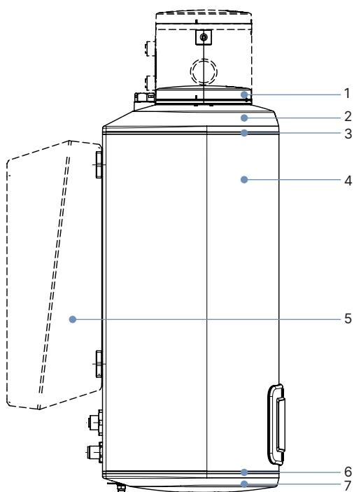
| Item No. | Actuator Component | Material |
|---|---|---|
| 1 | Display housing / blind cover | PPS (standard), stainless steel 1.4301 (for ATEX/IECEx) |
| 2 | Actuator cover | PPS |
| 3, 6 | Housing seals | EPDM |
| 4 | Actuator housing body | Powder-coated aluminium |
| 7 | Actuator base | PPS |
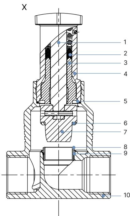
| Item No. | Fluidic Component | Material |
|---|---|---|
| 1 | Valve spindle | Stainless steel 1.4401 (316) / 1.4404 (316L) |
| 2 | Spindle seal pack | Solid PTFE V-seals with spring compensation |
| 3 | Spindle guide | Stainless steel 1.4404 (316L) |
| 4 | Packing gland tube | Stainless steel 1.4401 (316) |
| 5 | Valve body joint seal | Graphite or PTFE |
| 6 | Seat seal disc | PEEK (Polyetheretherketone) seal washer |
| 7 | Control cone | Stainless steel 1.4571 (316Ti) |
| 8 | Replaceable valve seat | Stainless steel 1.4571 (316Ti) |
| 9 | Seat O-ring | EPDM or PTFE |
| 10 | Valve body | Cast stainless steel CF3M (316L equivalent) |
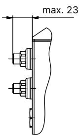
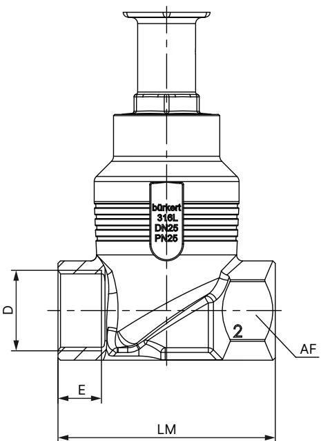
| Connection DN | Thread D | Thread Depth E [mm] | Body Face-to-Face LM [mm] | Wrench Flat AF [mm] | Total Height H1 [mm] |
|---|---|---|---|---|---|
| DN 10 (NPS 3/8) | G 3/8 | 12.0 | 65 | 27 | 417 |
Mechanical Dimensions Note
In the closed valve position without tight closing function, the actuator is raised by approximately 2 mm. Recommended installation position is upright with the actuator facing upwards, although any mounting attitude is permissible.
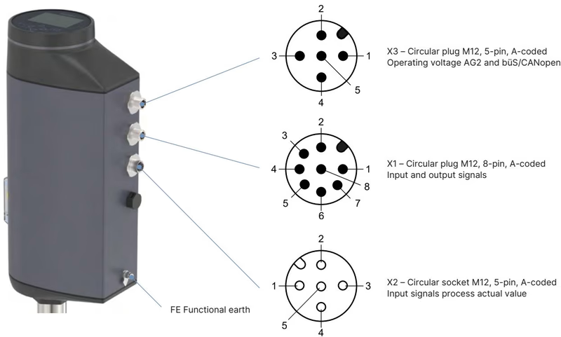
Article 362825 features an AG2 actuator equipped with M12 circular connectors for analogue control signals (X1) and 24 V DC power supply / büS networking (X3).
| Pin | Signal Assignment | Functional Characteristics |
|---|---|---|
| 1 | Digital input + | 0 to 5 V = log "0", 10 to 30 V = log "1" |
| 2 | GND (Digital) | Common ground for digital input and digital outputs |
| 3 | Digital output 2 + | PNP transistor output, current limited to 100 mA |
| 4 | Digital output 1 + | PNP transistor output, current limited to 100 mA |
| 5 | Analogue output - | Galvanically isolated analogue feedback ground |
| 6 | Analogue output + | 0/4 to 20 mA (load 0 to 800 Ω) or 0 to 5/10 V (max. 10 mA) |
| 7 | Setpoint input - | Analogue setpoint input negative terminal |
| 8 | Setpoint input + | 0/4 to 20 mA (input resistance 70 Ω) or 0 to 5/10 V (22 kΩ) |
| Pin | Signal Assignment | Description |
|---|---|---|
| 1 | CAN Shield | Cable shield connection |
| 2 | Supply voltage + | 24 V DC ±10% |
| 3 | GND / CAN_GND | Power supply ground and CAN reference |
| 4 | CAN_H | Bürkert system bus CAN high signal |
| 5 | CAN_L | Bürkert system bus CAN low signal |
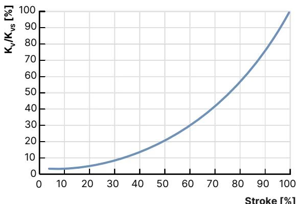
Article 362825 uses an equal-percentage control contour conforming to DIN EN 60534-2-4 with a theoretical rangeability of 50:1. The intermediate flow coefficients measured with water under flow below seat (2 → 1) conditions are defined below.
| Stroke [%] | Kv Value [m³/h] | Relative Capacity [%] |
|---|---|---|
| 10% | 0.007 | 0.56% |
| 20% | 0.011 | 0.88% |
| 30% | 0.045 | 3.60% |
| 40% | 0.085 | 6.80% |
| 50% | 0.160 | 12.8% |
| 60% | 0.260 | 20.8% |
| 70% | 0.410 | 32.8% |
| 80% | 0.650 | 52.0% |
| 90% | 1.100 | 88.0% |
| 100% | 1.250 | 100.0% |
Operating Limits on Media and Seat Seal
PEEK soft seal washers provide tight Class VI shut-off across a medium temperature span of -10 °C to +150 °C (continuous capability up to +230 °C). The maximum operating pressure is 25 bar(g) across all stroke positions. In contrast to metal-to-metal seating, no supplementary shut-off valve is required in the pipeline.
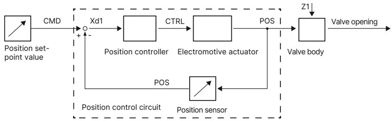
An internal contactless displacement transducer continuously detects the linear position (POS) of the drive spindle. The digital positioner compares POS against the external setpoint command (CMD) specified via the 4 to 20 mA or büS input. Any control deviation (Xd1) triggers the motor electronics via manipulated variable CTRL to drive the brushless motor until deviation falls within the ±0.1% dead band.
Article 362825 includes the factory-installed SAFEPOS energy-pack capacitive storage module. When line power fails, stored electrical energy drives the brushless motor into the defined fail-safe position:
Critical Service Warnings
Explore similar products in our catalog