PN25

BURKERT 20120984 Type 2961 is a manual 2-way globe control valve with 3/4" NPT thread, DN20 body, 10 mm seat, equal percentage 50:1 characteristic, and PN25 stainless steel construction.
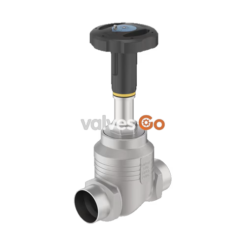
BURKERT 20120984 Type 2961 is a manually operated 2-way globe control valve engineered for precision fluid throttling and tight shut-off in demanding industrial applications. The assembly consists of a manual actuator crafted from polyphenylene sulphide (PPS) and a stainless steel 316L/CF3M globe body with an exchangeable seat. Configured under article number 20120984, the valve features a 3/4" NPT female threaded connection (DN 20), a 10 mm (3/8") orifice seat, and an equal percentage parabolic plug yielding a rated flow coefficient Kv of 2.8 m³/h (Cv 3.2 gal/min) with a theoretical rangeability of 50:1.
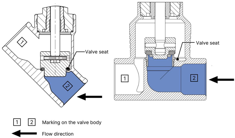
Fluid flows below the seat to ensure smooth opening control across differential pressures up to 25 bar. Tight zero-leakage shut-off corresponds to Leakage Class VI per DIN EN 60534-4 through a soft PTFE seat seal. The stem seal utilizes spring-compensated, filled PTFE V-rings that automatically compensate for wear without requiring manual repacking. The manual actuator integrates a 45 mm handwheel (Size S) with 50 division marks and an optical position indicator revealing a reproducible stroke scale for repeatable manual flow adjustments.

BURKERT 20120984 operates across liquid, gas, and steam media including demineralized water, alcohols, fuels, hydraulic oils, saline solutions, lyes, and organic solvents up to a kinematic viscosity of 600 mm²/s.
| Parameter | Specification |
|---|---|
| Valve Type | 2-way globe control valve (Type 2961) |
| Article Number (SKU) | 20120984 |
| Nominal Port Size | DN 20 (NPS 3/4") |
| Port Connection Type | Internal thread, NPT (ASME B1.20.1) |
| Nominal Seat Diameter | 10 mm (3/8") |
| Flow Direction | Flow to open (under seat) |
| Operating Pressure Range | 0 bar(g) to 25 bar(g) |
| Nominal Pressure Class | PN 25 (DIN EN 1333), Class 150 (DIN EN 1759) |
| Seat Leakage Class | Class VI (PTFE soft seal, DIN EN 60534-4:2006) |
| Medium Temperature Range | -10 °C to +130 °C (PTFE seat seal) |
| Ambient Temperature Range | -10 °C to +60 °C |
| Storage Temperature | -20 °C to +65 °C |
| Actuator Interface | Spindle D10 |
| Flow Characteristic | Equal percentage, 50:1 rangeability |
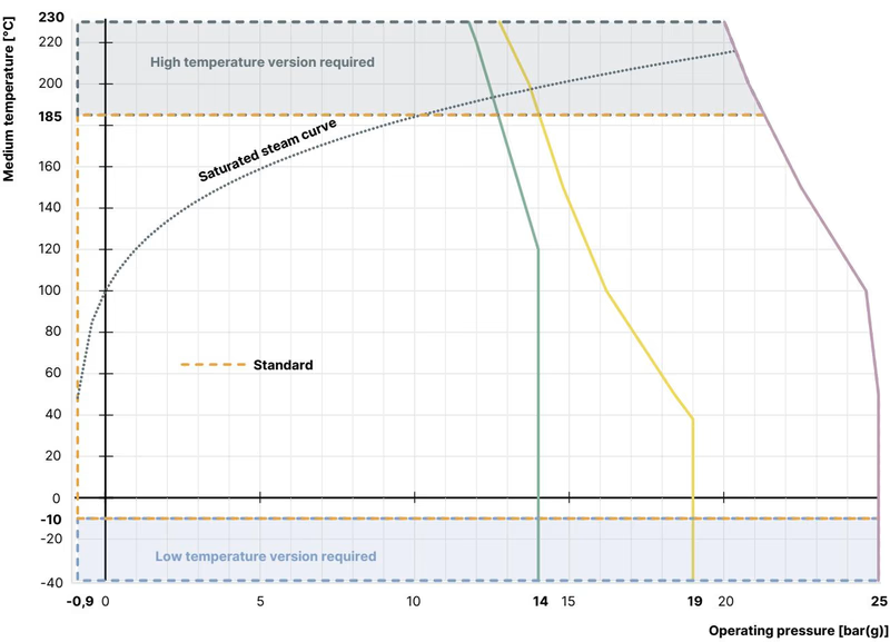
Operating pressure limits are subject to thermal derating according to the respective piping standards.
| Temperature [°C] | DIN EN 12516-1 / PN25 [bar] | ASME B16.34 Cl. 150 [bar] | JIS B 2220 10K [bar] |
|---|---|---|---|
| -10 to +38 / +50 | 25.0 | 19.0 | 14.0 |
| 100 | 24.5 | 16.2 | 14.0 |
| 130 (PTFE limit) | ~23.2 | ~15.4 | ~13.7 |
| 150 | 22.4 | 14.8 | 13.4 |
| 200 | 20.3 | 13.7 | 12.4 |
| 230 | 19.0 | 12.7 | 11.7 |
| Seat Seal Material | Leakage Class | Medium Temperature | Operational Note |
|---|---|---|---|
| PTFE (Configured on 20120984) | Class VI | -40 °C to +130 °C | Soft seal for bubble-tight shut-off; recommended for temperatures ≤ +130 °C |
| PEEK (Optional) | Class VI | -10 °C to +230 °C | Soft seal for tight shut-off; recommended for operating temperatures > +130 °C |
| Stainless Steel 1.4571 (Optional) | Class II | -40 °C to +230 °C | Metallic seal allows 0.5% nominal leakage; wear may accelerate under manual spindle rotation |
Fluid reaches the underside of the plug so the valve opens against media pressure, preventing pressure surges and chatter during low-flow throttling.
The parabolic trim geometry provides an equal percentage characteristic per DIN EN 60534-2-4. For seat sizes > 10 mm, the KvR limit is evaluated at 5% stroke; for seat sizes ≤ 10 mm, it is evaluated at 10% stroke.
| Seat Size [mm] | Handwheel [mm] | Max Pressure [bar] | Rangeability | 5% | 10% | 20% | 30% | 40% | 50% | 60% | 70% | 80% | 90% | 100% | Kvs [m³/h] |
|---|---|---|---|---|---|---|---|---|---|---|---|---|---|---|---|
| 10 (SKU 20120984) | 45 (S) | 25 (VI) | 50:1 | 0.10 | 0.12 | 0.15 | 0.19 | 0.30 | 0.46 | 0.67 | 1.0 | 1.5 | 2.1 | 2.8 | 2.8 |
| 15 | 45 (S) | 25 (VI) | 50:1 | 0.13 | 0.17 | 0.21 | 0.32 | 0.48 | 0.71 | 1.0 | 1.5 | 2.3 | 3.4 | 4.4 | 4.4 |
| 20 | 45 (S) | 25 (VI) | 50:1 | 0.19 | 0.24 | 0.29 | 0.42 | 0.64 | 0.97 | 1.4 | 2.0 | 2.9 | 4.2 | 5.9 | 5.9 |
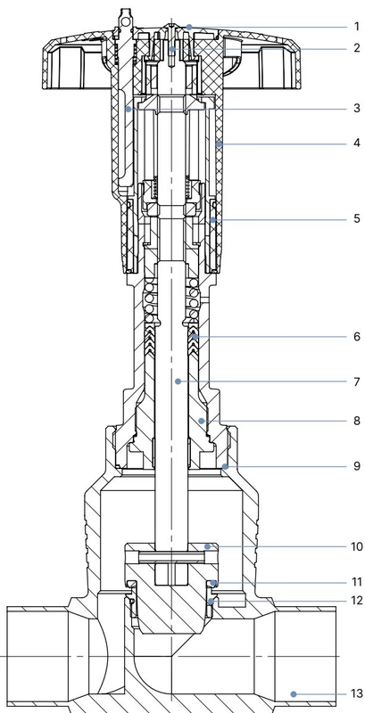
All wetted parts are built from corrosion-resistant austenitic stainless steels and inert polymer seals.
| Item | Component | Material |
|---|---|---|
| 1 | Cover | Polyamide (PA) |
| 2 | Screw | Stainless steel 1.4301 |
| 3 | Locking device (optional) | Stainless steel 1.4305 |
| 4 | Handwheel | Polyphenylene sulphide (PPS) |
| 5 | Position indicator with scale | Polyamide (PA) |
| 6 | Packing gland | Filled PTFE V-rings, spring-compensated |
| 7 | Stem | Stainless steel 1.4401 or 1.4404 |
| 8 | Spindle guide | Stainless steel 1.4404 (316L), PTFE filled |
| 9 | Housing seal | Graphite |
| 10 | Control cone | Stainless steel 1.4571 (optionally hardened) |
| 11 | Seat seal | PTFE (PEEK optional) |
| 12 | Valve seat with O-ring | Stainless steel 1.4571, EPDM |
| 13 | Valve body | Stainless steel 316L / CF3M |
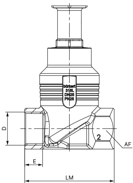
| Pipe Size DN | Pipe Size NPS | Handwheel Diameter [mm] | H1 [mm] | H2 with Locking [mm] |
|---|---|---|---|---|
| 15 | 1/2 | 45 (S) | 217 | 224 |
| 20 (SKU 20120984) | 3/4 | 45 (S) | 224 | 230 |
| 25 | 1 | 45 (S) | 228 | 234 |
| 32 | 1 1/4 | 110 (M) | 296 | 303 |
| 40 | 1 1/2 | 110 (M) | 301 | 307 |
| 50 | 2 | 110 (M) | 307 | 313 |
| 65 | 2 1/2 | 160 (L) | 361 | 368 |
| 80 | 3 | 160 (L) | 369 | 375 |
| 100 | 4 | 160 (L) | 379 | 385 |
All dimensions are stated in millimeters.
| DN | NPS | E [G] | E [NPT] | E [Rc] | LM | AF (Wrench Flat) |
|---|---|---|---|---|---|---|
| 10 | 3/8 | 12.0 | 10.3 | 10.1 | 65 | 27 |
| 15 | 1/2 | 14.0 | 13.7 | 13.2 | 65 | 27 |
| 20 | 3/4 | 16.0 | 14.0 | 14.5 | 75 | 34 |
| 25 | 1 | 18.0 | 16.8 | 16.8 | 90 | 41 |
| 32 | 1 1/4 | 20.0 | 17.3 | 19.1 | 110 | 50 |
| 40 | 1 1/2 | 22.0 | 17.3 | 19.1 | 120 | 55 |
| 50 | 2 | 24.0 | 17.6 | 23.4 | 150 | 70 |
| 65 | 2 1/2 | 26.0 | 23.7 | 26.7 | 185 | 85 |
| 80 | 3 | 28.0 | 30.5 | 29.8 | 205 | 100 |
| 100 | 4 | 32.0 | 33.0 | 35.8 | 240 | 125 |
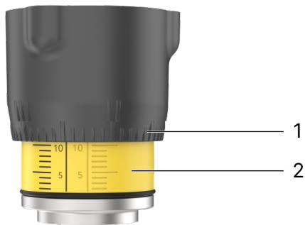
Turning the handwheel counterclockwise lifts the spindle and opens the valve. Turning clockwise drives the plug down onto the seat. For Handwheel Size S (45 mm diameter), spindle lead is 1.25 mm per complete turn, and total rated stroke for DN 20 is 19 mm.
INFO
The visibility of the stroke scale is not directly tied to the absolute seated closure. Depending on valve tolerances, the scale lines may remain slightly visible when fully seated, or become hidden before full travel.
WARNING
Do not rely on the handwheel locking pin in the closed position to ensure specified leakage tightness under fluctuating thermal or pressure loads. Close the valve firmly by hand before engaging locking pins.
| Valve Body Nominal Size DN | Tightening Torque [Nm] | Tolerance [Nm] |
|---|---|---|
| 10 / 15 | 45 | ±3 |
| 20 (SKU 20120984) | 50 | ±3 |
| 25 | 60 | ±3 |
| 32 / 40 | 65 | ±3 |
| 50 | 70 | ±3 |
| 65 | 100 | ±3 |
| 80 | 120 | ±5 |
| 100 | 150 | ±5 |
High Pressure Hazard
Depressurize and drain pipelines completely before unscrewing the actuator or removing the valve body from the pipe network.
Body Connection Loosening
In systems subjected to severe pipeline vibration or medium temperatures above 140 °C, the threaded body joint may relax. Inspect and verify union tightness at regular maintenance intervals.
Under normal operating parameters, the PPS manual actuator is completely maintenance-free. Perform an annual visual inspection across the external envelope.
| Symptom | Probable Cause | Corrective Action |
|---|---|---|
| Valve does not seal tightly | Dirt/debris trapped between seal and seat | Clean seating surface; install upstream strainer |
| Valve does not seal tightly | PTFE seat seal worn or damaged | Replace closure member / seat seal kit |
| Valve does not seal tightly | Reversed flow direction | Reinstall valve matching cast flow arrow |
| Valve does not seal tightly | Differential pressure exceeds rated limit | Verify system pressure against rating label (25 bar max) |
| Fluid leaks from relief bore | Packing gland V-rings worn | Replace stem packing gland assembly |
When ordered with variable code PX51, BURKERT Type 2961 is certified as non-electrical mechanical equipment (constructional safety) suitable for Zone 1/21 and Zone 2/22:
| Temperature Class | Permissible Surface Temperature | Ambient Temperature Range | Maximum Medium Temperature |
|---|---|---|---|
| T2 | 300 °C | -40 °C to +130 °C | +285 °C |
| T3 | 200 °C | -40 °C to +130 °C | +185 °C |
| T4 | 135 °C | -40 °C to +100 °C | +125 °C |
Electrostatic Discharge Hazard
Electrostatic charge accumulation presents an explosion hazard. The valve body must be grounded to the piping installation. Ground all conductive parts using an approved grounding strap or terminal clip. Clean the polymer actuator housing exclusively with a damp or antistatic cloth.
Low-Conductivity Media Restrictions
For fluids with electrical conductivity ≤ 100 pS/m, maintain flow velocity ≤ 1 m/s and ensure lines remain completely flooded to avoid static generation inside the valve body.
Explore similar products in our catalog