Type 2032

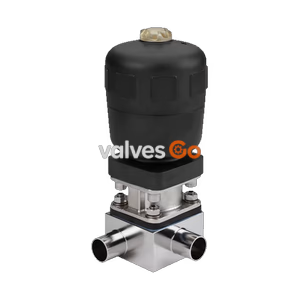
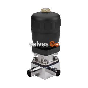
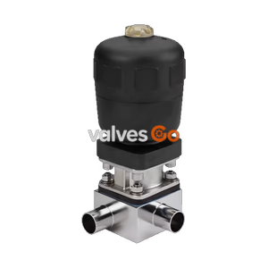
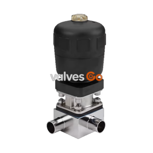
BURKERT 20099064 (Type 2032) pneumatic 3/2 diaphragm T-valve features a PPS CLASSIC actuator, Advanced PTFE/EPDM diaphragm, and ASME BPE DN 65 x DN 25 weld ports for zero-deadleg hygienic loops at 0 to 10 bar.
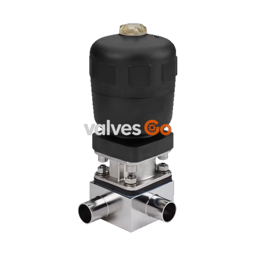
BURKERT 20099064 (Type 2032) is an externally controlled pneumatic 3/2-way diaphragm T-valve engineered for high-purity, sterile, aggressive, or abrasive fluid handling in hygienic processing facilities. The unit consists of a CLASSIC pneumatic piston actuator enclosed in polyphenylene sulphide (PPS), an Advanced PTFE/EPDM backing diaphragm, and a machined stainless steel block T-body. Designed to eliminate stagnant deadlegs in distribution loops, the valve integrates directly into a 2 1/2 inch (DN 65) ASME BPE run line while providing a 25 mm body orifice for sampling, draining, or branch feeding. It operates under normally closed Control Function A with media pressures from 0 bar to 10 bar.
The CLASSIC actuator features a compact, autoclavable PPS housing suitable for sterile process environments and chemically aggressive ambient washdown areas. The actuator includes an integrated optical position indicator as standard and uses FKM internal piston seals.
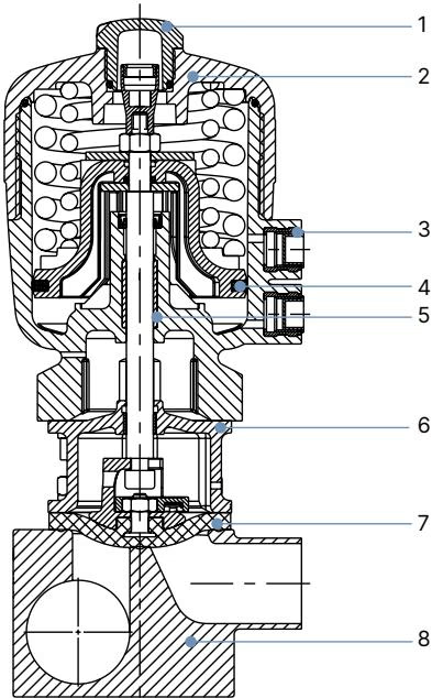
| Item | Component | Material |
|---|---|---|
| 1 | Transparent cap | Polysulfone (PSU) |
| 2 | Actuator cover | Polyphenylene sulphide (PPS standard, PA on request) |
| 3 | Pilot air ports | Stainless steel 1.4305 |
| 4 | Piston seal | Fluor rubber (FKM) |
| 5 | Socket | Sintered metal |
| 6 | Interface | Stainless steel 1.4404 |
| 7 | Diaphragm | EPDM (AD), PTFE/EPDM (EA), Advanced PTFE/EPDM (EU), GYLON®/EPDM laminate (ER) |
| 8 | Valve body | Stainless steel block 1.4435 (DIN EN 10088) / 316L (ASME BPE Table MM-2.1.1) |
BURKERT 20099064 operates with Control Function A (SFA), closing by spring force in the unpressurised state. Compressed air supplied to the lower control port moves the piston upward against the return springs to open the valve orifice.
| Parameter | Specification |
|---|---|
| Control function | Control Function A (CF A, normally closed by spring force) |
| Pilot media | Neutral gases, air |
| Pilot air pressure range | 5.5 bar to 7.0 bar (actuator size 80 mm / F) |
| Media working pressure | 0 bar to 10 bar (static differential pressure) |
| Medium temperature (Advanced PTFE/EPDM EU) | -5 °C to +143 °C (steam sterilisation up to +150 °C for 60 min) |
| Actuator ambient temperature (PPS <= 80 mm) | +5 °C to +140 °C |
| Flow medium capability | Neutral gases, liquids, high-purity, sterile, aggressive, or abrasive media |
Maximum Working Pressure for Control Function A
For diaphragm size 25 with actuator size 80 mm (F) and pilot pressure between 5.5 bar and 7.0 bar, the maximum static operating pressure is 10 bar for both elastomeric (EPDM/FKM) and fluoropolymer (PTFE/EPDM, Advanced PTFE/EPDM EU) diaphragms.
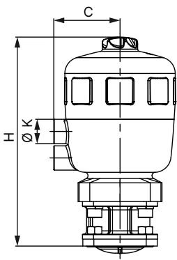
| Diaphragm Size | Actuator Size Ø | Ø A (mm) | C (mm) | K (Air Port) | H (mm) | HM + MT85 (mm) |
|---|---|---|---|---|---|---|
| 8 | 40 (C) | 53 | 34 | G 1/8 | 111 | 207 |
| 15 | 50 (D) | 64 | 39 | G 1/8 | 137 | 233 |
| 15 | 63 (E) | 80 | 52 | G 1/4 | 154 | 249 |
| 20 | 63 (E) | 80 | 52 | G 1/4 | 165 | 261 |
| 20 | 80 (F) | 101 | 52 | G 1/4 | 186 | 281 |
| 25 | 80 (F) | 101 | 60 | G 1/4 | 190 | 286 |
| 40 | 100 (G) | 127 | 73 | G 1/4 | 246 | 339 |
| 40 | 125 (H) | 158 | 86 | G 1/4 | 284 | 377 |
| 50 | 100 (G) | 127 | 73 | G 1/4 | 254 | 347 |
| 50 | 125 (H) | 158 | 86 | G 1/4 | 288 | 381 |
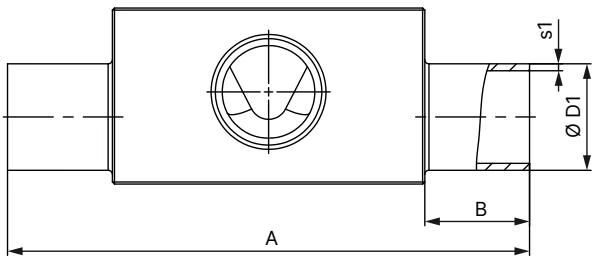
Dimensions for T-valve block bodies with ASME BPE weld ends (diaphragm size 25):
| Diaphragm Size | Run DN to Branch DN | ØD1 (mm) | s1 (mm) | ØD2 (mm) | s2 (mm) | A (mm) | B (mm) | C (mm) | E (mm) | F (mm) | G (mm) | H (mm) | I (mm) | Product Key |
|---|---|---|---|---|---|---|---|---|---|---|---|---|---|---|
| 25 | 25 to 25 | 25.40 | 1.65 | 25.40 | 1.65 | 124.5 | 25 | 74.8 | 25 | 95 | 42 | 26 | 6.0 | SODF-SODF |
| 25 | 40 to 25 | 38.10 | 1.65 | 25.40 | 1.65 | 124.5 | 25 | 81.1 | 25 | 103 | 58 | 36 | 16.0 | SODH-SODF |
| 25 | 50 to 25 | 50.80 | 1.65 | 25.40 | 1.65 | 134.5 | 30 | 87.5 | 25 | 120 | 75 | 44 | 24.0 | SODI-SODF |
| 25 | 65 to 25 | 63.50 | 1.65 | 25.40 | 1.65 | 134.5 | 30 | 93.8 | 25 | 129 | 82 | 47 | 27.0 | SODJ-SODF |
| 25 | 80 to 25 | 76.20 | 1.65 | 25.40 | 1.65 | 134.5 | 30 | 100.15 | 25 | 142 | 94 | 52 | 32.0 | SODK-SODF |
Note: Dimensions correspond to BURKERT 20099064 specification (Port 1: 63.50 mm OD / DN 65 ASME BPE; Port 2: 25.40 mm OD / DN 25).
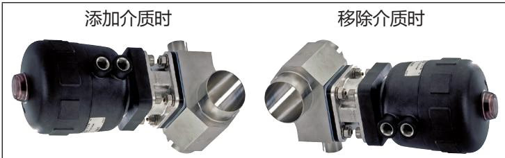
Loop Installation and Drainability
When installing the Type 2032 T-valve into a distribution loop, position the leak detection monitoring hole in the diaphragm bonnet at the lowest physical point. Keep pipeline gradient between 1° and 5° to ensure complete self-draining performance.
Welding Safety Requirements
Natural wear parts are the diaphragm and actuator seals. Inspect the overflow leak detection hole at regular intervals for process media discharge. Check the diaphragm for wear at intervals not exceeding 100,000 switching cycles.
| Diaphragm Size | PTFE / Advanced PTFE EU | EPDM / FKM / GYLON® Laminate |
|---|---|---|
| 8 | Push-in button | Push-in button |
| 15 to 20 | Bayonet mount | Bayonet mount |
| 25 to 65 | Bayonet mount | Threaded connection |
For BURKERT 20099064 (Diaphragm size 25 with Advanced PTFE EU diaphragm), the connection utilises a bayonet lock. Rotate the diaphragm 90° to disengage from the spindle.
During assembly of Control Function A valves, apply control pressure to the lower pilot air port to retract the spindle. Position the new diaphragm into the actuator so that the identification tab is oriented perpendicular to the direction of flow. Place the assembly onto the body, tighten screws loosely in a crosswise pattern, cycle the valve twice, release pilot pressure, and tighten screws crosswise in three steps (1/3, 2/3, 3/3 of final torque value).
| Diaphragm Size (DN) | Cast / Forged / Block Bodies (VS/VG) EPDM/FKM (Nm) | Cast / Forged / Block Bodies (VS/VG) PTFE/EU/ER (Nm) | Tube Valve Bodies (VA/VP) EPDM/FKM (Nm) | Tube Valve Bodies (VA/VP) PTFE/EU/ER (Nm) |
|---|---|---|---|---|
| 8 | 2.0 | 2.5 | 2.5 | 2.5 |
| 15 | 3.5 | 4.0 | 3.5 | 4.0 |
| 20 | 4.0 | 4.5 | 4.0 | 4.5 |
| 25 | 5.0 | 6.0 | 7.0 | 8.0 |
| 32 | 6.0 | 8.0 | 8.0 | 10.0 |
| 40 | 8.0 | 10.0 | 12.0 | 15.0 |
| 50 | 12.0 | 15.0 | 15.0 | 20.0 |
| 65 | 20.0 | 30.0 | 20.0 | 30.0 |
Note: Torque values have a tolerance of +10%. For BURKERT 20099064 (stainless steel block body, diaphragm size 25, Advanced PTFE diaphragm), target tightening torque is 6.0 Nm.
BURKERT 20099064 (Type 2032) can be combined with electrical position feedback units or control heads to create complete automated valve stations:
Explore similar products in our catalog